Category Archives: Natural Gas Industry

Oil Barrels and Dollar Signs

Efficiency & Compliance Drive Industrial Energy Profits in 2026

Two key phrases you will hear often this year from any executive in the energy sector are “capital discipline” and “cost reduction”. Translation for asset integrity managers, operations managers, project engineers, and welders: get more life and value out of what you’ve already got… despite a moving regulatory target and tougher operating conditions. 

Whether you’re scaling up natural gas production or decommissioning some wells, modern equipment should be designed for ease of installation and include artificial intelligence that protects your asset against downtime. 

Today’s production facilities must operate under an expanding range of wellhead pressures, temperatures, and flow volumes. Intelligent solutions require rugged hardware designed for direct exposure to raw natural gas — and smart software that can alert you to critical component wear before it causes a shutdown.

Modular Separation and Multi-Phase Filtration 

Whether you’re conditioning gas from a stripper well or maximizing recovery from a tight oil play, every production facility is only as good as its separation and filtration hardware. Self-contained, skid-mounted two-phase and three-phase separators are faster to install AND scale with changing well flow volumes.

  • Two-phase and three-phase separators prevent expensive liquid carryover with innovative internals like cyclonic inlet ports and high-volume mist extractors.
  • Filter separators remove particulates like dirt, rust, and pipe scale down to .5 microns to protect sensitive processing equipment.
  • If you’re working with high-BTU gas, a JT skid could increase productivity by recovering natural gas liquids (NGLs) and stabilizing the methane number of your fuel gas.

Pro Tip: Run “bottlenecks” through your compression assets. Our proprietary AI can alert you to upcoming performance issues 72 hours before normal sensors even trigger the alarm.

“Digital Is Operational” in 2026 

Remote and unmanned production sites require equipment that integrates with existing site infrastructure to give you real-time asset performance. Pro-Gas designs and builds each of our solutions with a robust network of industrial IoT sensors. Real-time data delivered to your connected devices lets you see your asset like never before.

With a “digital twin” of your physical asset modeled in the cloud, your engineers can visualize operational performance at any pressure/T loads. Soon enough, AI will be applied to energy vibration signatures and heat emissions to predict a critical component’s failure before it happens. This could reduce O&M costs by up to 20%.

Pro Tip: Actively Monitor Changing Regulations in 2026

Safety officers and EHS professionals understand that change is the only constant in environmental regulations. Just this year, the EPA published final rules amending the New Source Performance Standards (NSPS) for stationary combustion turbines in January.

  1. Existing equipment will be expected to comply with revised NOX emission standards.
  2. Compliance managers are scrambling to meet the first of two upcoming OSHA Hazard Communication Standard (HCS) deadlines, set for May 19 and November 20, 2026. 
  3. All equipment manufacturers will be expected to audit labels for completeness and certify they’re GHS Revision 7 compliant across their site.
  4. Vapor recovery units (VRUs) are popping up on tank batteries to recover “flash gas” that was previously flared or vented into the atmosphere.

Your 60-Second Compliance Audit 

Ask yourself three questions to see where you can improve compliance right now.

  • Do your equipment labels meet the latest GHS Revision 7 standards? If not, you have until May 19th of 2026. 
  • Are your separators equipped with sensors to detect liquid droplets getting past the demister and into the fuel gas line?
  • When was the last time your maintenance team performed service based on a calendar date, rather than IoT sensor input?

Call On Pro-Gas LLC | Partner For Long-Term Productivity

Pro-Gas believes your well is our well. That’s why we take the time to understand your production challenges and provide thoughtful recommendations to meet your business goals. Our comprehensive product catalog features everything from field gas conditioners and JT skids to portable NGL storage to help you keep more revenue at the wellhead. 

More than 90 years of professional experience is at your service from our San Antonio-based engineers and technicians. Contact us to streamline gas storage, verify your site is hydrogen-ready, or just to ensure your processes are optimized for runtime and runtime communications.

Frequently Asked Questions (FAQ) 

Q. What is a JT skid and how can it improve the quality of my fuel gas?

JT skids use the Joule-Thomson Effect to reduce the temperature of incoming high-BTU gas. As the gas cools, heavier hydrocarbons and liquids condense out of the gas stream, lowering BTU and dew point values. Once stabilized, your waste gas can be used as high-quality engine and turbine fuel.

Q. Why should I choose modular skid-mounted equipment? 

Prefabricated skids can be installed in a fraction of the time compared to traditional equipment. They’re also portable for quick turnover between sites and require less square footage for storage. Plus, everything needed to operate is built into one “plug and play” unit.

Q. How does predictive maintenance help my operations stay profitable?

Most plants and facilities use IoT sensors, but few are using those sensors to their full advantage. By analyzing energy vibration signatures and heat emissions with AI, you can plan maintenance around critical components BEFORE they fail and cause unscheduled downtime. Studies show this practice can decrease O&M expenses by up to 20%.


Natural Gas Production Facility Equipment

The Future of Fuel Gas Conditioning: Trends and Innovations

Conditioning raw gas at the wellhead used to mean “meet pipeline specifications.” Now, conditioning has grown to encompass everything you can do to protect high-dollar downstream assets and operate within capital discipline parameters. 

This year has placed additional importance on how operations managers and technical engineers can wring the most productivity out of every cubic foot of fuel gas while limiting routine maintenance events on rotating equipment. 

As industrial energy systems grow in complexity, so too should your strategy for treating that fuel. Let’s take a look at what’s coming down the pike.

Advanced Fuel Gas Conditioning Strategies 

From next-generation filtration to digital oversight, you can help future-proof your processing plant with these three fuel gas conditioning tips.

1. Improve Filtration & Separation 

Removal of liquid water and contaminants should always be your first line of defense in fuel gas conditioning, but legacy approaches can be improved with membrane separation technology and enhanced particulate filtration media.

  • Membranes vs Glycol: While glycol dehydration units are still very common, membrane separation systems offer operators a smaller footprint and zero volatile organic compound (VOC) emissions. The latest membrane skids offer up to 95% water removal efficiencies and require far less maintenance than traditional thermal regeneration units.
  • Solids and NGL Removal: Don’t let solids or natural gas liquids (NGLs) entering your compressor units go untreated. Similarly, if your gas stream feeds into an acid gas removal unit (AGRU), removing NGLs and solids before absorption can improve overall downstream asset performance. Avoid unnecessary unplanned shutdowns by removing solids and NGLs at the source.
  • Manage BTU Content: High-BTU gas can negatively impact engine performance through “knock” or turbine derating. Modern multi-stage conditioning skids can chill incoming gas down to -50°F using a Joule-Thomson (JT) valve and heat exchanger network. Dropping your fuel temperature removes heavy hydrocarbons, allowing you to maintain a consistent methane number (MN).

2. Transition to Digital Twins 

Digitally monitoring fuel gas conditioning trains isn’t new. What is new, however, is the transition from reactive asset maintenance to fully predictive oversight via digital twin technology.

Digital twins are essentially a real-time digital replica of a process asset or plant. Developing a digital twin of your fuel gas conditioning train lets operators test “what-if” scenarios and model proposed plant configurations without risk to actual assets. 

Aggregating IoT sensor data (vibration, temperature, differential pressure) through a digital twin interface can help detect deviations from nominal performance before they occur. 

Since these models isolate and analyze data patterns too small for human operators to notice, routine maintenance can evolve to fully predictive maintenance schedules. Asset health monitoring through predictive AI could reduce your unplanned downtime by half.

Tip: Are you constantly battling the same “bottlenecks” in your compression assets? Predictive, prescriptive AI can alert you to impending inefficiencies 72 hours before the lowest performing sensor in your network will.

Including AI predictive models in your regular maintenance schedule could decrease unplanned downtime by 30% to 50%. What’s more, total asset lifespan could see a 40% increase due to the regulatory agility and high-level oversight provided by these platforms. Predictive monitoring will be tablestakes for most processing facilities this year.

Hydrogen Blend Preparation 

The race to lower-carbon energy is coming to fuel gas treatment systems in the form of hydrogen blending.

  1. Audit your hydraulic assets for hydrogen compatibility.  All seals and piping should be screened for hydrogen compatibility. While most polyethylene (PE) piping can handle up to 20% hydrogen blending without issue, you may find your metallic valves and pumps require special coatings.
  2. Instruments will need to be upgraded.  Hydrogen isn’t methane, so your gas chromatographs and flow meters should be able to measure hydrogen BTU values in real-time. Otherwise, your combustion turbines could run too “rich” and avoid damaging turbine blades.
  3. Adjust your pressure regulation ramps.  Hydrogen has a lower molecular density than methane, which means your compression and pressure regulation values should be increased proportionally. Failure to account for this can result in your end-use equipment seeing wildly fluctuating levels of energy.

Take 60 Seconds to Check Compliance

Ask yourself these three questions to determine if your gas conditioning is prepared for 2026 safety standards.

  • Do your gas conditioning skids have IoT-enabled sensors for methane leak detection?
  • Do you find yourself making more “emergency” repairs, as opposed to scheduled maintenance events?
  • Is your existing infrastructure hydrogen-ready for 5%-to-10% blends?

If you answered no to any of the above questions, now is the time to reach out to your local processing equipment supplier. Ensuring your fuel gas is properly conditioned before it enters your pipe network can reduce maintenance costs and prevent catastrophic failure.

Call On Pro-Gas LLC | Excellence In Long-Term Productivity

Don’t let the technical jargon of fuel gas conditioning scare you into making expensive or unnecessary changes to your plant. When facing pressure from downtimes and regulatory mandates, who you choose as your partner can make all the difference. 

At Pro-Gas, our engineers specialize in custom skid-mounted JT plants and fuel gas conditioning solutions to treat your gas at the source. Contact us today to learn how you can maximize NGL recovery, reduce maintenance costs, and prepare your assets for tomorrow’s industrial energy landscape.

Frequently Asked Questions

Q. How will fuel gas conditioning affect my turbine efficiency?  

Condensing water vapor and heavy hydrocarbons before they reach your turbines ensures consistent BTU content while preventing liquid water carryover. Liquid droplets can pit turbine blades and disrupt ideal combustion temperatures.

Q. What are the advantages of using a membrane dehydration system?  

Membrane systems are modular and require very little maintenance. They also completely eliminate the need for chemical solvents and fire-tube reboilers used in glycol dehydration units. Just keep in mind that membrane systems aren’t as efficient or proven as glycol dehydration.

Q. Can I retrofit my existing conditioning skid for hydrogen?  

Yes, most skids can be upgraded with new sensors, hydrogen-friendly valves, and modified control logic. Our team can help you audit your current systems for compatibility with hydrogen rich-gas streams.

Fuel Gas Conditioning Skid

The Role of Dehydrators in Preventing Pipeline Corrosion

In the high-stakes environment of energy production, the integrity of our transport systems is paramount. At Pro-Gas, we recognize that while pipelines are the veins of the industry, they are constantly under threat from a silent, invisible enemy: moisture. When untreated natural gas travels through carbon steel lines, the presence of water vapor is not just an efficiency concern, it’s the primary catalyst for internal degradation.

Let’s walk through the critical function of natural gas dehydrators and how they serve as the first line of defense against infrastructure failure. We will examine the chemical processes that lead to decay, the various technologies used to extract moisture, and the long-term benefits of maintaining a dry system. By the end of this guide, you will understand why high-quality dehydration is the most cost-effective insurance policy for your operation.

The Silent Threat | Understanding Internal Pipeline Corrosion

When we talk about pipeline corrosion, we are often referring to the electrochemical reaction that occurs when liquid water settles on the interior surface of a pipe. In the oil and gas sector, this is rarely “pure” water. It is typically a brine solution that, when combined with acidic gases like Carbon Dioxide (CO2) or Hydrogen Sulfide (H2S), creates a highly corrosive environment.

Without the intervention of dehydrators, these contaminants react with the steel to form iron carbonates or sulfides, leading to “pitting” — a localized form of damage that can cause pinhole leaks or catastrophic ruptures. By removing the water, we effectively remove the medium required for these chemical reactions to take place. Consider linking to our article on [internal corrosion monitoring] to learn how to detect these issues before they escalate.

The Chemistry of Wet Gas

  • Acid Gas Formation | When CO2 dissolves in water, it forms carbonic acid, which aggressively attacks carbon steel.
  • Microbial Induced Corrosion (MIC) | Stagnant water provides a breeding ground for sulfate-reducing bacteria (SRB) that accelerate metal loss.
  • Oxygen Contamination | Even trace amounts of oxygen in a wet system can exponentially increase the rate of oxidation.

Engineering a Solution | How Dehydrators Function

To combat these threats, we employ natural gas dehydrators designed to meet stringent pipeline quality standards, often referred to as “tariff gas” (typically containing less than 7 lbs of water per million cubic feet). These systems work by utilizing the principles of absorption or adsorption to strip water molecules from the gas stream.

The Absorption Process | Glycol Dehydration

The most prevalent technology in our industry is the glycol dehydration unit. This system uses a liquid desiccant, usually Triethylene Glycol (TEG), which has a powerful natural affinity for water.

  • Contacting | Wet gas enters the bottom of a contactor tower and rises through trays or packing. Simultaneously, “lean” (dry) glycol is pumped into the top and flows downward.
  • Absorption | As the gas and glycol meet, the glycol “soaks up” the water vapor.
  • Regeneration | The now “rich” (wet) glycol is sent to a reboiler where it is heated to approximately 400°F. The water is boiled off as steam, and the purified glycol is recirculated.

This continuous loop ensures that the gas exiting the top of the tower is dry and ready for safe transport. For more information on thermodynamic properties of glycols, consider linking to The Engineering ToolBox for more information.

The Adsorption Process | Solid Desiccant Dehydrators

In scenarios where extremely low dew points are required—or for remote locations where a reboiler flame is undesirable—we utilize solid desiccant dehydrators. These units pass gas through a bed of porous material like silica gel or molecular sieves. The water molecules adhere to the surface of the desiccant through a process called adsorption.

Beyond Decay | Preventing Hydrates and Blockages

While pipeline corrosion is a major focus, dehydrators also solve the problem of hydrate formation. Gas hydrates are ice-like crystalline structures that form when water and hydrocarbons combine under specific temperature and pressure conditions.

These “ice plugs” can completely block a pipeline, leading to costly emergency shutdowns and potential safety hazards during removal. By maintaining a water dew point well below the lowest ambient temperature of the pipeline, we ensure that hydrates never have the chance to form.

The Pro-Gas Advantage | Integrated Moisture Management

At Pro-Gas, we believe that equipment should work in harmony. Our natural gas dehydrators are designed to integrate seamlessly with our other production technologies, such as JT Skids and portable NGL storage. This holistic approach ensures that not only is the water removed, but valuable natural gas liquids (NGLs) are captured and managed efficiently.

By choosing our specialized dehydration packages, you are investing in the longevity of your assets. We have seen firsthand how a properly sized and maintained dehydrator can extend the life of a gathering system by decades, saving operators millions in replacement costs and environmental remediation.

Enhance Your Production with Pro-Gas

The role of dehydrators in our industry cannot be overstated. By effectively removing moisture, these machines prevent the devastating effects of pipeline corrosion, eliminate the risk of hydrate blockages, and ensure that the gas meets the high-quality standards required by end-users.

Is your current system struggling with moisture carryover or high maintenance costs? Contact our engineering team today to request a site-specific evaluation. We can help you size the perfect dehydration package to protect your pipelines and maximize your production uptime.

FAQ | Frequently Asked Questions

Q. How often should I test my glycol in a TEG dehydrator?

We recommend performing a comprehensive glycol analysis at least once every six months. This test should check for pH levels, water content, and the presence of hydrocarbons or salt, which can indicate internal issues or the need for a “reclaiming” process.

Q. Why is H2S particularly dangerous in a wet pipeline?

Hydrogen Sulfide (H2S) reacts with liquid water to form sulfuric acid and iron sulfide. This not only causes rapid pipeline corrosion but can also lead to “hydrogen blistering” or “sulfide stress cracking,” which can cause sudden structural failure of the pipe wall.

Q. Can I use a dehydrator to remove more than just water?

While their primary goal is water removal, glycol dehydrators can also capture small amounts of BTEX (Benzene, Toluene, Ethylbenzene, and Xylene) and other volatile organic compounds. However, if the goal is specialized contaminant removal, additional gas sweetening or filtration stages may be required.

bi-fuel gas conditioner / Dual Fuel Gas Treatment

Comparing Different Types of Compressors

The equipment we choose dictates the efficiency of our entire worksite. At Pro-Gas, we have spent decades refining our approach to gas production facility equipment, and we know that the heart of any reliable operation is its compression system. Whether you are managing a high-pressure wellhead or a low-pressure vapor recovery project, choosing the right compressor is not just a technical decision — it’s a financial one.

Let’s explore the various technologies available to modern operators. We will look at how each type of machine functions, where they excel, and how to identify the perfect fit for your specific operational goals. From the rugged reliability of reciprocating units to the continuous power of rotary screws, understanding these differences is the first step toward maximizing your uptime and revenue.

The Role of Compression in Modern Operations | Reciprocating Compressors

When we discuss the “workhorse” of the industry, we are almost always talking about reciprocating compressors. These machines function through a positive displacement process, using pistons driven by a crankshaft to reduce the volume of gas and increase its pressure. They are uniquely suited for applications where high pressure is a non-negotiable requirement.

For many of our clients, the reciprocating model is the go-to choice for wellhead compression and gas lift operations. Because they can handle high compression ratios, they allow us to move gas from low-pressure reservoirs into high-pressure pipelines with ease. Consider linking to our article on multi-stage compressor installation to see how these units are integrated into complex systems.

Advantages of Reciprocating Technology

  • High Pressure Capabilities | These units can achieve pressures up to 5,000 PSIG and beyond, making them essential for deep-well applications.
  • Flexibility | They can handle varying gas compositions and flow rates more effectively than some of their centrifugal counterparts.
  • Efficiency at High Ratios | When the difference between suction and discharge pressure is significant, reciprocating units are often the most energy-efficient option.

Operational Considerations

While powerful, these machines involve more moving parts — such as valves, rings, and packings — which necessitates a consistent maintenance schedule. We always recommend that operators keep a close eye on vibration levels, as the pulsing nature of the piston movement can stress piping if not properly dampened.

Continuous Flow for Mid-Range Needs | Rotary Screw Compressors

For operations that require a steady, pulsation-free flow of gas, rotary screw compressors offer a modern and highly efficient alternative. These machines use two intermeshing helical screws (rotors) to trap and compress gas. Unlike the “stop-and-start” motion of a piston, the rotary action is continuous.

We often deploy these units in vapor recovery units (VRUs) or for fuel gas conditioning. Because they have fewer wearing parts than a reciprocating unit, they typically boast longer intervals between major overhauls. This makes them an excellent choice for remote locations where frequent technician visits are difficult or costly. For more technical specifications on rotor design, consider linking to Engineering ToolBox for more information.

Why Operators Choose Rotary Screws

  • 100% Duty Cycle | These machines are designed to run 24/7 without the need for frequent cooling breaks.
  • Low Vibration | The smooth rotation leads to a much quieter and more stable operation, which simplifies the structural requirements of your skid.
  • Compact Footprint | Rotary screws are often smaller than reciprocating units of the same capacity, which is a major benefit for offshore platforms or cramped site layouts.

Potential Drawbacks

While they are fantastic for mid-pressure applications, rotary screws typically cannot reach the extreme high-pressure levels that a multi-stage reciprocating unit can. Additionally, they are sensitive to particulates in the gas stream, meaning high-quality filtration is a must.

Handling Mass Volumes | Centrifugal Compressors

When the priority is volume rather than extreme pressure, centrifugal compressors take the lead. These are dynamic compressors that use a high-speed rotating impeller to add kinetic energy to the gas, which is then converted into pressure energy as it passes through a diffuser.

In the large-scale pipeline transmission sector, centrifugal units are the industry standard. They can move massive amounts of gas with incredible efficiency. However, for most localized field operations or individual wellheads, the scale and cost of a centrifugal system may be more than what is required.

Key Benefits of Centrifugal Units

  • Massive Flow Rates | If you are moving millions of cubic feet per day, no other technology can compete.
  • Oil-Free Gas | Because the lubrication system is separated from the gas path, there is no risk of oil carryover into the pipeline.
  • Lower Maintenance per MCF | While the initial investment is high, the lack of rubbing parts in the compression chamber leads to very long service lives.

Specialized Solutions | Rotary Vane Compressors

A less common but highly effective option for specific tasks is the rotary vane compressors. These use a rotor with several blades inserted into slots. As the rotor turns, centrifugal force pushes the blades against the cylinder wall, creating chambers of decreasing volume to compress the gas.

We find that vane compressors are particularly useful for low-pressure applications, such as gathering gas from older, depleted wells. They are incredibly simple in design and are known for their durability in “dirty” gas environments where other compressors might fail due to contamination.

How to Choose the Best Compressor for Your Operation

Selecting the right unit requires more than just looking at a spec sheet. We recommend a step-by-step approach to evaluate your site’s specific needs.

Step 1 | Define Your Pressure and Flow Requirements

Start by determining your suction pressure (what is coming out of the well) and your required discharge pressure (what the pipeline or facility requires). If you need to jump from 50 PSI to 1,200 PSI, a multi-stage reciprocating unit is likely your best bet. If you need high volume at a steady 300 PSI, a rotary screw might be the winner.

Step 2 | Analyze Your Gas Composition

Is your gas “sour” (containing H_{2}S)? Is it heavy with natural gas liquids (NGLs)? Reciprocating units are generally more forgiving with varying gas weights, while rotary screws require very clean, dry gas to prevent rotor damage. If you are dealing with high NGL content, our JT Skids can help condition the gas before it ever reaches the compressor.

Step 3 | Evaluate the Environment

Remote locations demand reliability and low maintenance. If you cannot get a mechanic to the site within four hours, a rotary screw’s longer service intervals become a massive advantage. Conversely, if you are in a cold climate, you need to consider how the lubrication and cooling systems will perform at -20°F.

Step 4 | Consider Future Growth

Don’t just buy for today. If you expect your well’s pressure to drop over the next two years, you need a compressor that can be easily re-cylindered or adjusted to handle those changing conditions. Flexibility is a hallmark of Pro-Gas equipment designs.

Maximize Your Investment with Pro-Gas

At Pro-Gas, we don’t just provide hardware; we provide operational certainty. Our fleet includes specialized compressed natural gas packages and portable NGL storage solutions designed to work in tandem with your compression strategy. By choosing the right compressor and pairing it with our state-of-the-art conditioning equipment, you can significantly reduce the risk of downtime.

We believe storytelling in the oilfield is often written in the data of our daily production logs. When we see a client’s revenue increase because we switched them to a more efficient rotary screw VRU, that is a story of success we are proud to be part of. Our goal is to make your production as smooth and profitable as possible.

The Path to Optimal Performance

Comparing different types of compressors reveals that there is no “one size fits all” solution in the oil and gas industry. The best machine for your operation depends entirely on your specific pressure needs, flow volumes, and maintenance capabilities. Whether it is the high-pressure muscle of reciprocating compressors, the steady reliability of rotary screw compressors, the massive scale of centrifugal compressors, or the niche durability of rotary vane compressors, each has a vital role to play.

By taking the time to analyze your site requirements and consulting with experts who understand the nuances of gas production, you can select a system that not only meets today’s demands but also positions you for long-term growth.

Take the Next Step with Pro-Gas

Ready to optimize your site’s performance? Contact our team today to discuss our custom compression packages and how we can tailor a solution to your specific wellhead conditions. Let us help you maximize your runtime and protect your bottom line.

FAQ | Frequently Asked Questions

Q. Which compressor is most efficient for high-pressure gas lift?

Reciprocating compressors are generally the most efficient for high-pressure gas lift because they can handle high compression ratios and provide the necessary discharge pressure to overcome wellbore hydrostatic head.

Q. Can rotary screw compressors handle “wet” gas?

Rotary screw compressors are sensitive to liquids and particulates. While they are highly efficient, they usually require upstream conditioning, such as a scrubber or a JT skid, to remove NGLs and moisture before the gas enters the compression chamber.

Q. What are the main maintenance differences between reciprocating and centrifugal units?

Reciprocating units require more frequent maintenance of valves, pistons, and seals due to their mechanical design. Centrifugal units have fewer contacting parts in the gas stream, leading to longer periods between major service intervals, though their specialized components can be more expensive to repair when needed.


bi-fuel gas conditioner / Dual Fuel Gas Treatment

Implementing Vapor Recovery Units to Comply with Environmental Regulations

The energy industry is undergoing a fundamental shift. For decades, our primary focus was solely on getting hydrocarbons out of the ground and into the pipeline. Today, however, the scope of our operations has expanded. We are no longer judged merely by our production volumes but by our stewardship of the resource and our adherence to an increasingly complex web of rules. At Pro-Gas LLC, we recognize that for modern operators, implementing vapor recovery units is no longer an optional “green” initiative; it is a license to operate.

The regulatory environment surrounding methane emissions reduction and Volatile Organic Compounds (VOCs) is tightening rapidly. From the federal level down to state agencies, the mandate is clear: capture the gas or shut in the well. This pressure can feel overwhelming, but we view it through a different lens. We see compliance as an opportunity for operational improvement. By capturing the rich vapors that flash off storage tanks, we not only meet the letter of the law but also capture a valuable revenue stream that was previously vanishing into thin air.

In this post, let us explore the intricacies of environmental regulations affecting the oil and gas sector and how the strategic deployment of VRU technology serves as the ultimate solution. We will examine the technical challenges of low-pressure compression, the financial realities of compliance, and the operational best practices that guarantee uptime. We want to guide you through turning a regulatory burden into a fixed asset.

The Regulatory Climate | Understanding EPA Quad O And Beyond

To navigate the current landscape, we must first understand the rules of the engagement. The driving force behind the push for vapor recovery units is the Environmental Protection Agency’s (EPA) New Source Performance Standards, specifically 40 CFR Part 60, Subpart OOOO, commonly referred to as “Quad O,” and its subsequent updates, Quad Oa, Ob, and Oc.

These regulations specifically target fugitive emissions and venting from crude oil and natural gas facilities. The core requirement dictates that storage vessels with the potential to emit (PTE) 6 tons or more of VOCs per year must reduce those emissions by 95 percent. In practical terms, this means that for the vast majority of producing wells—especially in the Permian, Eagle Ford, and Bakken basins—venting tank vapors to the atmosphere is illegal.

The consequences of non-compliance are severe. Beyond the substantial fines, which can reach tens of thousands of dollars per day per violation, there is the risk of forced shut-ins. We have seen operators lose significant production days because they failed to have a compliance strategy in place before an audit. Furthermore, the new “Super Emitter” program empowers third parties to report large emission events, putting operators under a microscope like never before.

What Is A VRU? | The Anatomy Of Flash Gas Recovery

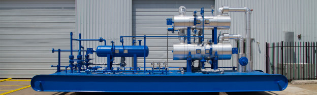
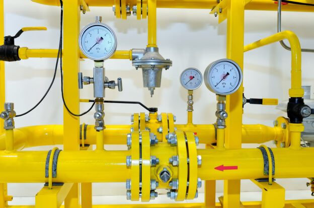
A Vapor Recovery Unit (VRU) is essentially a compression system designed for a very specific, low-pressure application. Unlike a standard wellhead compressor that might take gas at 50 PSI and boost it to 1000 PSI, a VRU must pull gas from storage tanks at mere ounces of pressure and boost it high enough to enter the low-pressure gathering system or the suction side of a larger compressor.

The process begins with flash gas recovery. When crude oil is dumped from a high-pressure separator into a generic atmospheric storage tank, the sudden pressure drop causes light hydrocarbons (methane, ethane, propane, butane) to “flash” out of the liquid phase and become gas. Without a VRU, this gas builds pressure in the tank until it vents through the thief hatch or pressure relief valve.

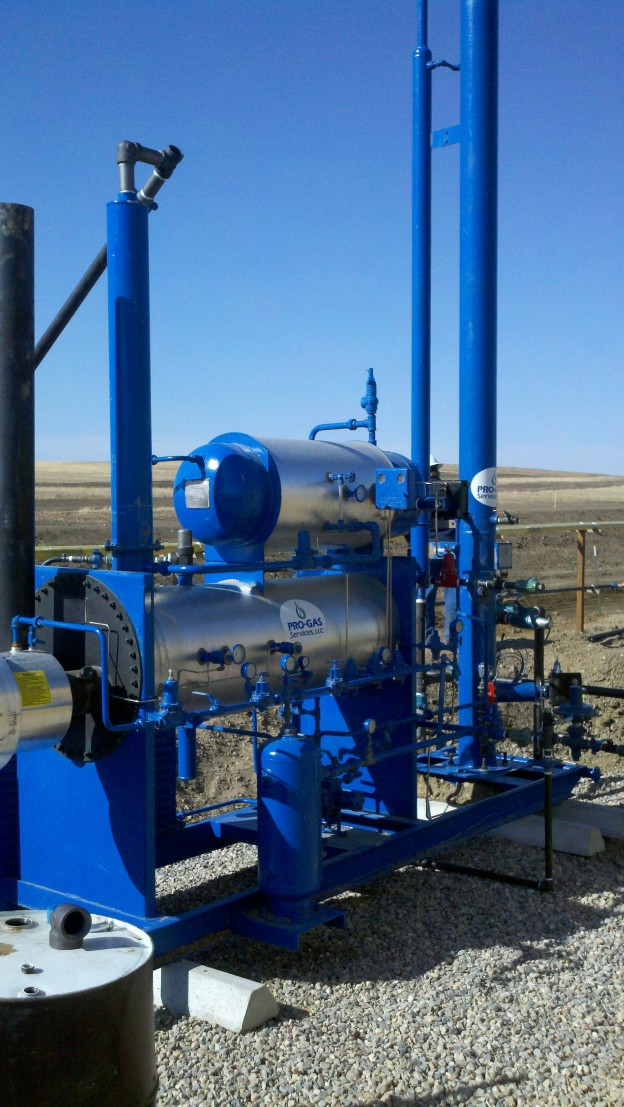
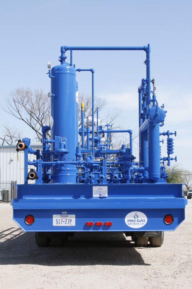
A Pro-Gas LLC VRU system typically consists of:

  1. Suction Scrubber: To remove any liquid carryover from the tanks.
  2. Compressor: Usually a rotary vane or screw compressor, chosen for its ability to handle wet, rich gas.
  3. Driver: An electric motor or natural gas engine.
  4. Bypass Valve: To recirculate gas when tank pressure is too low, preventing the unit from pulling a vacuum.
  5. Automation Control Panel: The brain of the system that monitors tank pressures and adjusts the compressor speed.

The technical challenge here is stability. Storage tanks are not pressure vessels; they are designed to hold liquid at atmospheric pressure. Pulling too much suction can collapse a tank (implosion), while failing to pull enough allows venting. Therefore, the precision of the VRU technology is paramount.

Selecting The Right Tech | Rotary Vane vs. Screw For VRUs

When we design a solution for compliance strategy, the choice of compressor type is critical. The two dominant technologies in this space are rotary vane and rotary screw compressors. Each has its place, but for many field applications, we lean heavily on specific designs based on the gas analysis.

Rotary vane compressors are exceptional for flash gas recovery in smaller to medium-sized batteries (volumes from 20 Mcfd up to 500 Mcfd). Their sliding vane design allows them to handle “wet” gas—gas heavily saturated with natural gas liquids (NGLs)—without damage. The oil injected into the cylinder coats the vanes and cylinder walls, protecting them from the corrosive elements often found in tank vapors, such as Hydrogen Sulfide (H2S).

Screw compressors are typically utilized for larger central facilities where the vapor volume is high (over 500 Mcfd) and relatively consistent. They offer high efficiency and smooth flow but can be more sensitive to particulates and liquids.

At Pro-Gas LLC, we assess the specific “richness” of the gas. Tank vapors are often incredibly rich, with BTU values exceeding 2000. This makes them valuable, but it also makes them dangerous for standard engines due to detonation risks. We verify that the driver—whether electric or gas—is rated to handle the fuel quality or that the facility has a separate fuel gas scrubber to provide lean gas to the engine.

Operational Efficiency | Managing Variable Flow Rates

The biggest enemy of operational efficiency in vapor recovery is the variable nature of the flow. Tank vapors do not generate at a constant rate. They surge when a dump valve opens on a separator and slow down when the separator closes. They also fluctuate wildly with ambient temperature; a hot summer day generates significantly more vapor than a cold winter night.

To maintain EPA Quad O compliance, the VRU must react instantly to these changes. If the unit is too slow to speed up, the tank pressure spikes and the thief hatch vents—a violation. If it is too slow to slow down, it pulls a vacuum, risking oxygen ingress.

We utilize Variable Frequency Drives (VFDs) on electric motors and sophisticated governor controls on gas engines to achieve this. A VFD allows the compressor to ramp its speed up and down millisecond-by-millisecond based on a pressure transducer on the tank. This “turndown” capability allows us to match the compressor’s displacement exactly to the vapor generation rate, securing a steady tank pressure of typically 2 to 4 ounces.

Consider linking to our previous discussion on Variable Frequency Drives for more technical insights.

The Danger Of Oxygen | Safety And Compliance

One of the most critical aspects of implementing vapor recovery units that we emphasize to every client is oxygen management. Because VRUs draw from atmospheric tanks, there is a constant risk of pulling air (oxygen) into the system if the pressure drops below zero (vacuum).

Oxygen in a gas stream is a catastrophic issue. First, it creates an explosive mixture. Second, most pipelines have strict tariff limits (often 10 ppm) for oxygen. If you push oxygen-laden gas into the sales line, the midstream company will shut you in.

To combat this, our systems utilize redundant safety shutdowns. We set a “low suction pressure” kill switch that shuts the unit down instantly if pressure approaches 0.5 ounces. Additionally, we recommend the installation of oxygen sensors on the discharge line. These sensors act as a final gatekeeper, shutting down the VRU and isolating the sales line if oxygen is detected. This attention to detail is what separates a basic install from a true Pro-Gas LLC solution.

Financial Metrics | The ROI Of Capture

While the impetus for installing a VRU is often environmental regulations, the financial argument is equally compelling. We encourage operators to look at the Return on Investment (ROI) of capture.

Let us run a hypothetical scenario based on a typical Permian battery:

  • Vapor Volume: 100 Mcf/day.
  • Gas Price: $2.50/Mcf (conservative).
  • BTU Factor: 2.0 (Tank vapors are very rich).
  • Realized Price: $5.00/Mcf (due to BTU uplift).
  • Daily Revenue: $500.
  • Annual Revenue: $182,500.

A standard VRU installation might cost between $80,000 and $120,000 depending on infrastructure needs. In this scenario, the unit pays for itself in less than eight months. After that, it generates pure profit.

This calculation does not even factor in the avoidance of fines. A single EPA fine for fugitive emissions can exceed the cost of the entire VRU system. When you combine the revenue from the gas with the risk mitigation of compliance, the decision to install VRU technology becomes a financial no-brainer.

Handling Liquids | The Wet Gas Challenge

Tank vapors are “wet,” meaning they are on the verge of falling back into liquid phase. When we compress these vapors, the increase in pressure and subsequent cooling in the discharge line causes NGLs to drop out. If not managed, these liquids can flood the compressor or slug the downstream facility.

We design our systems with robust scrubbing and temperature control. We often install a discharge scrubber after the compressor to catch these liquids. This “compressor condensate” is extremely high-gravity, valuable oil. We utilize automatic dumps to pump this liquid back into the oil storage tanks or a pressurized bullet tank.

If we fail to manage this liquid, it can dilute the compressor oil, leading to bearing failure. We implement a rigorous oil analysis program for all our VRU fleets. By monitoring the viscosity and dilution of the oil, we can adjust the operating temperatures (running the compressor hotter helps keep water in vapor phase) to extend the life of the equipment.

Scaling With Production | Modularity

One common mistake we see is oversizing. An operator expects a new three-well pad to produce massive volumes, so they install a giant VRU. When the wells decline, the unit is too big to run efficiently, constantly shutting down on low suction. Conversely, undersizing leads to venting during peak production.

We advocate for a modular approach to methane emissions reduction. Instead of one massive unit, it is often better to install two smaller units or a unit with a very wide turndown ratio. As production declines, we can easily swap the compressor for a smaller frame size while keeping the same skid and driver. This flexibility allows the compliance strategy to evolve with the life of the well.

At Pro-Gas LLC, we maintain a fleet of various sizes. We can deploy a 50 HP unit for initial flush production and swap it for a 20 HP unit six months later. This adaptability verifies that you are not paying for horsepower you do not need, while still capturing every cubic foot of gas.

Monitoring And Reporting | Verifying Compliance

Installing the unit is step one. Proving that it works is step two. Under EPA Quad O, operators must maintain records of the time the VRU was operating and any downtime events. If the VRU is down for maintenance and the tanks are venting, that volume must be calculated and reported.

We equip our units with telemetry that logs suction pressure, discharge pressure, and run status. This data is fed into the operator’s SCADA system. This digital trail is your insurance policy during an audit. It proves that you were capturing gas 98 or 99 percent of the time.

Furthermore, we assist in calculating the capture efficiency. By analyzing the run-time data against the theoretical GOR (Gas-Oil Ratio) of the well, we can provide reports that satisfy state and federal agencies. This data-driven approach removes the guesswork from oil and gas regulatory compliance.

Maintenance Best Practices | Keeping The VRU Online

A VRU is the hardest working compressor in the field. It runs 24/7/365 (ideally). To maintain this schedule, we implement strict maintenance protocols.

  • Daily: Check oil levels and scrubber dumps. A stuck dump valve can flood the compressor in minutes.
  • Monthly: Check belt tension and alignment. The varying loads from the VFD can cause belt fatigue.
  • Quarterly: Calibrate pressure transducers. If the sensor drifts by just one ounce, it can cause venting or vacuum issues.

We also pay close attention to the bypass valve. This valve modulates to recirculate gas. If the seat wears out, hot gas leaks back to suction, causing the unit to overheat. Regular inspection of these control valves is essential for operational efficiency.

Consider linking to our Guide on Compressor Maintenance Schedules.

The Future Of Emissions | Zero Flaring

The industry trend is moving toward “Zero Flaring.” Major operators are pledging to eliminate routine flaring by 2030. Implementing vapor recovery units is the cornerstone of this ambition. We are moving toward a future where the only time a flare is used is during genuine emergency safety events.

We are also seeing the rise of “instrument air” systems powered by these VRUs. Instead of using methane to actuate pneumatic valves (which vent methane every time they stroke), operators are using compressed air. However, for remote sites, we can utilize the compressed gas from the VRU (dried and scrubbed) to power these devices, creating a closed-loop system that vents nothing to the atmosphere.

Optimize Your Business with Pro-Gas

The implementation of Vapor Recovery Units is the intersection of responsibility and profitability. We have navigated the complex requirements of environmental regulations, dissected the mechanics of flash gas recovery, and proven the financial viability of these systems.

At Pro-Gas LLC, we do not just rent compressors; we provide compliance strategies. We understand that every ounce of pressure matters and that every minute of downtime is a liability. By choosing the right VRU technology, sizing it correctly, and maintaining it with rigor, we help you navigate the regulatory waters with confidence.

Do not view the EPA mandates as a hindrance. View them as a challenge to optimize. Let us capture that value together.

Stop venting profits and start capturing value. Contact Pro-Gas LLC today to design a Vapor Recovery solution that guarantees compliance and boosts your bottom line.

FAQ | Vapor Recovery And Compliance

  1. What triggers the requirement for a VRU under EPA Quad O regulations?

The requirement is triggered based on the Potential to Emit (PTE) of the storage vessels. If a single storage tank or a battery of tanks has the potential to emit 6 tons or more of Volatile Organic Compounds (VOCs) per year, the operator must reduce these emissions by at least 95 percent. While flaring is a method of reduction, capturing the gas with a Vapor Recovery Unit (VRU) is the preferred method for both economic recovery and emissions reduction.

  1. How does a VRU handle the liquids found in wet tank vapors?

VRUs designed for wet gas, such as rotary vane compressors, handle liquids through a combination of robust scrubbing and oil injection. The suction scrubber removes the bulk of the free liquid before it enters the compressor. Inside the compressor, injected oil seals the compression chamber and protects the metal surfaces from corrosion. Furthermore, the discharge temperature is maintained high enough to prevent water from condensing inside the compressor oil, while discharge scrubbers capture any hydrocarbons that fall out after compression, pumping them back to the storage tanks.

  1. Can a VRU system completely eliminate the need for a flare?

While a VRU is designed to capture 95 to 100 percent of the routine vapor production, it does not completely eliminate the need for a flare or a combustor. A flare is still required as a safety relief device. In the event of a mechanical failure of the VRU, a power outage, or a massive slug of gas that exceeds the VRU’s capacity, the gas must have a safe outlet. The VRU and flare work in tandem: the VRU handles the daily load to maximize revenue and minimize emissions, while the flare stands by for emergency relief.

Compressed Natural Gas

Maximizing Throughput | How High-Performance Gas Compressors Boost Productivity in Gas Processing

In the energy sector, efficiency isn’t just a buzzword: it’s the metric that determines survival and profitability. At Pro-Gas LLC, we have walked the lease roads, monitored the gauges, and analyzed the flow rates alongside you. We understand that every minute of downtime translates to lost revenue and operational headaches that ripple through the entire supply chain. The heart of this operation often lies in a single, critical piece of machinery: the compressor.

The difference between breaking even and achieving record profitability often comes down to the reliability and output of your compression fleet. When we talk about high-performance gas compressors, we are looking at the technological backbone that supports the entire midstream and upstream ecosystem. These are not merely engines; they are precision instruments designed to handle the specific variances of wellhead gas, maintain pressure, and facilitate the transport of hydrocarbons to market.

In this post, let’s explore how upgrading to or maintaining elite compression systems drives productivity. We will look at the mechanical advantages, the operational strategies, and the bottom-line impacts of utilizing top-tier equipment. We want to help you verify that your facility is not just running, but sprinting.

The Mechanics Of Productivity | Understanding The Role Of Compressors

To understand how to boost productivity, we must first look at the physics and engineering that define our daily operations. Gas compression is fundamentally about thermodynamics and fluid dynamics. The goal is to increase the pressure of the gas by reducing its volume, preparing it for transport or processing. However, standard compressors often struggle with the variable nature of field gas, which can contain liquids, heavy hydrocarbons, and corrosive elements.

We have seen too many operators rely on outdated technology that was never designed for the wet, rich gas profiles common in modern shale plays. This mismatch leads to constant tripping, valve failures, and inefficient compression cycles. High-performance gas compressors are engineered to handle these discrepancies. They utilize advanced metallurgy and superior valve designs that can withstand higher temperatures and pressures without degrading.

Consider the story of a facility in the Permian Basin we worked with last year. They were utilizing generic reciprocating units that were constantly overheating due to high ambient temperatures and rich gas streams. By switching to a unit specifically designed for optimizing natural gas production in hot climates, featuring oversized cooling systems and heavy-duty scrubbers, they increased their runtime by 14 percent in the first quarter alone. That is the tangible power of using the right tool for the job.

Types Of High-Performance Tech | Rotary Vane vs. Screw Compressors

Selecting the right equipment is the first step toward efficiency. Two of the most common high-performance options we encounter are rotary vane and screw compressors. Understanding the nuance of rotary vane vs screw compressors is vital for matching the machine to the application.

Rotary vane compressors are workhorses. They operate using a rotor with slots and vanes that slide in and out, trapping gas and compressing it as the volume decreases. They are exceptionally good at handling wet gas and sour gas applications because the oil injection seals the vanes and protects the metal from corrosion. For lower pressure, high-volume applications, these units are often the superior choice because they have fewer moving parts and can operate for years with minimal intervention.

Screw compressors, on the other hand, use two meshing helical screws to compress the gas. They are typically more efficient at higher pressures and offer a smooth, pulse-free flow. This makes them ideal for applications where consistent flow rates are critical for downstream processing. However, they can be more sensitive to particulates and liquids.

When we assess a site for midstream gas processing technology, we look at the gas analysis first. If the stream is heavy with NGLs (Natural Gas Liquids), a rotary vane might offer better durability. If the gas is dry and needs a significant pressure boost to enter a sales line, a screw compressor or a high-speed reciprocating unit might be the answer. Making this distinction correctly is the first step in preventing the mechanical failures that kill productivity.

Reliability As A Revenue Driver | Reducing Downtime In Gas Processing

The most expensive compressor is the one that is not running. Operational uptime, or availability, is the gold standard of gas processing. We focus heavily on reducing downtime in gas processing because the cost of a shutdown goes beyond just the lost gas. It involves labor costs for repairs, potential flaring fines, and the risk of damaging the reservoir if wellhead pressure fluctuates too drastically.

High-performance units contribute to reliability through advanced diagnostics and robust construction. Modern compressors come equipped with telematics and sensors that monitor vibration, temperature, and pressure differentials in real-time. This allows for predictive maintenance rather than reactive repairs. Instead of waiting for a bearing to seize, we can see a temperature spike in the trend data and schedule a shutdown during a planned window.

We also emphasize the importance of auxiliary systems. A compressor is only as good as its lubrication and cooling systems. High-performance gas compressors often feature redundant oil pumps and advanced filtration systems that remove contaminants before they can damage the internal components. This attention to detail safeguards the asset and guarantees that the unit remains online when you need it most.

Strategic Implementation | Optimizing Natural Gas Production

Productivity is not just about keeping the machine running; it is about maximizing what flows through it. Optimizing natural gas production requires a holistic view of the facility. We often utilize high-performance compressors as part of a broader strategy to lower gathering system pressures.

By installing field booster applications at strategic points, we can lower the pressure at the wellhead. This reduction in backpressure allows the well to flow more freely, effectively increasing the production rate of the reservoir. We have utilized specific boosters designed to handle the initial surge of production while being flexible enough to turn down as the well declines.

This strategy requires compressors that have a wide operating envelope. Standard units often suffer from “turndown” issues, where they cannot run efficiently at lower flow rates. High-performance units often utilize variable frequency drives (VFDs) or slide valves to adjust the capacity of the compressor to match the incoming gas flow. This prevents the unit from recycling gas — a waste of energy — and maintains a steady suction pressure that maximizes well output.

The Environmental And Efficiency Nexus | Vapor Recovery Unit Efficiency

In today’s regulatory environment, capturing every molecule of gas is not just about profit; it is about compliance. Vapor Recovery Units (VRUs) are specialized compressors designed to capture low-pressure vapors from storage tanks that would otherwise be vented or flared.

Vapor recovery unit efficiency is a critical component of modern facility management. A high-performance VRU does more than just keep you compliant with EPA Quad O regulations; it turns a waste stream into a revenue stream. The vapors flashing off oil tanks are often very rich in BTUs, making them valuable if they can be compressed and pushed into the sales line.

However, VRU applications are notoriously difficult. The flow rate of vapor fluctuates wildly depending on ambient temperature and tank levels. We utilize high-performance VRUs with sophisticated logic controllers that can start and stop automatically or adjust speed instantly to match the vapor generation rate. This prevents oxygen ingress—which can ruin a load of gas—and guarantees that the tanks remain at a safe pressure.

Maximizing Output | NGL Recovery Solutions

Beyond standard compression, high-performance units play a pivotal role in NGL recovery solutions. Natural Gas Liquids (propane, butane, ethane) are often more valuable than the methane gas itself. To recover these liquids, the gas often needs to be compressed to high pressures and then cooled to drop the liquids out of suspension.

We employ compressors that are specifically tuned for the refrigeration cycles used in NGL recovery. These units must handle the specific refrigerants (often propane) without leaking or losing efficiency. A high-performance refrigeration compressor maintains the precise temperatures required to maximize liquid dropout.

If a compressor in an NGL plant fluctuates in performance, the temperature of the cold box rises, and those valuable liquids remain as gas and are sold at the lower heating value of methane. By utilizing top-tier midstream gas processing technology, we secure the temperature stability required to extract maximum value from the gas stream.

Preventative Maintenance For Gas Equipment

We cannot discuss performance without discussing care. The most advanced machine in the world will fail without a rigorous regimen of preventative maintenance for gas equipment. At Pro-Gas, we believe that maintenance should be proactive, not reactive.

A high-performance maintenance schedule includes:

  • Daily: Visual inspections for leaks, checking oil levels, and monitoring vibration monitors.
  • Monthly: Oil analysis. This is the blood work of the compressor. High levels of metal particulates indicate wear; high acidity indicates blowby or contamination.
  • Quarterly: Valve inspection and cleaning. In rotary vane vs screw compressors, the maintenance points differ, but the concept remains the same: keep the internals clean.
  • Annually: Full system audit, including cooler cleanings and alignment checks.

By adhering to these protocols, we extend the Mean Time Between Failures (MTBF). We have seen operators extend the life of their assets by years simply by being disciplined with their oil changes and filtration upgrades.

For specific checklists, consider linking to reputable industry maintenance guides like those from the Gas Processors Suppliers Association.

Field Booster Applications

In aging fields, reservoir pressure naturally declines. To keep these wells economic, we must artificially lower the line pressure. Field boosters are small, agile compressors that sit at the well site.

The challenge here is mobility and autonomy. These units often operate in remote locations without daily supervision. High-performance gas compressors used in this context must be rugged. We utilize units with auto-restart capabilities and remote telemetry. If a unit goes down due to a high-line pressure upset, it should be smart enough to restart once the condition clears, without requiring a pumper to drive two hours to push a button.

We helped a client in the Eagle Ford implementation a fleet of rotary vane boosters. By integrating these with a SCADA system, they achieved 99 percent compressor availability, revitalizing production from wells that were on the brink of being shut in.

Calculating ROI | The Financial Argument

When we propose an upgrade to high-performance equipment, the initial capital expenditure (CAPEX) is often higher than refurbishing an old unit. However, the return on investment (ROI) becomes clear when we look at reducing downtime in gas processing.

Here’s a simple scenario: A standard compressor goes down for 24 hours once a month.

  • Gas Flow: 1,000 Mcf/day.
  • Gas Price: $3.00/Mcf.
  • Loss: $3,000 per month, plus repair costs ($2,000).
  • Total Annual Loss: $60,000.

A high-performance unit might cost $20,000 more upfront but runs with 99.5 percent availability. The payback period is roughly four months. After that, the increased reliability is pure profit. When you factor in vapor recovery unit efficiency and the sale of captured NGLs, the financial argument for premium equipment is undeniable.

Operational Excellence | Midstream Gas Processing Technology

The integration of midstream gas processing technology goes beyond the compressor itself. It involves the scrubbers, the dehydration units, and the control systems. We approach the compressor skid as a unified ecosystem.

High-performance skids are designed with ergonomics and safety in mind. They feature easy access to maintenance points, which encourages operators to actually perform the checks. They utilize high-grade piping to minimize pressure drop between the scrubber and the cylinder. Every PSI of pressure lost to friction is money wasted on fuel gas.

We also focus on the “turn-down” capability. In the midstream sector, volumes are rarely constant. A facility might receive 50 MMcfd one day and 30 MMcfd the next due to upstream maintenance. High-performance compressors with automated pocket unloaders or variable speed drives can adjust to this flow without shutting down or flaring. This flexibility is the hallmark of operational excellence.

Securing the Future With Pro-Gas

The gas industry is evolving. We are moving toward tighter margins, stricter environmental regulations, and a higher demand for efficiency. The days of oversizing a cheap compressor and hoping for the best are over. Compressor availability is now a primary KPI for every asset manager.

By investing in high-performance gas compressors, you are investing in the longevity of your field. You are protecting your equipment from the harsh realities of field booster applications and ensuring that your NGL recovery solutions are operating at peak efficiency.

We have seen the transformation that occurs when an operator embraces this mindset. The panic of 2 AM alarms is replaced by the confidence of predictive monitoring. The loss of revenue from downtime is replaced by consistent, optimized throughput.

In the demanding environment of gas processing, your equipment is your lifeline. We have explored how high-performance gas compressors serve as the engine of productivity, driving everything from wellhead pressure reduction to vapor recovery unit efficiency. We compared rotary vane vs screw compressors to highlight the importance of application-specific selection and detailed the rigorous preventative maintenance for gas equipment required to keep these assets running.

Whether you are focused on optimizing natural gas production in the field or refining midstream gas processing technology at a central plant, the conclusion is the same: Quality pays. Reducing downtime, maximizing NGL recovery, and utilizing smart field booster applications are not just operational goals; they are financial necessities.

At Pro-Gas LLC, we are dedicated to providing the expertise and the technology to make this a reality for your operations. Do not let outdated equipment throttle your potential.

Ready to optimize your facility’s output and reliability? Contact Pro-Gas LLC today to discuss our high-performance compressor solutions tailored to your specific needs.

FAQ | Optimizing Gas Compression

Q. How do high-performance gas compressors specifically help in reducing downtime in gas processing?

High-performance gas compressors reduce downtime by utilizing advanced metallurgy, superior valve designs, and real-time telematics. These features allow the units to withstand harsh operating conditions and enable predictive maintenance. By identifying potential issues like temperature spikes or vibration before they cause failure, operators can schedule repairs during planned windows rather than suffering unexpected outages.

Q. What are the key differences to consider when choosing between rotary vane vs screw compressors?

The choice depends largely on the gas composition and pressure requirements. Rotary vane compressors are generally better suited for lower pressure, sour, or wet gas applications due to their robust sealing and tolerance for particulates. Screw compressors are typically preferred for higher pressure, high-volume applications where a smooth, pulse-free flow is required, though they are more sensitive to contaminants in the gas stream.

Q. Why is vapor recovery unit efficiency critical for modern gas facilities?

Vapor recovery unit efficiency is vital for both regulatory compliance and profitability. Efficient VRUs capture methane and hazardous volatile organic compounds (VOCs) that would otherwise be vented, preventing environmental fines. Furthermore, these captured vapors are often rich in BTUs, meaning they can be compressed and sold, turning a regulatory liability into a revenue-generating asset for the operator.

JT Skid for Fuel Conditioning

Bringing Order to Chaos | A Pro Gas Guide to the Different Types of Gas Separators

The journey of hydrocarbons begins deep within the earth, and when they finally reach the surface, they emerge as a turbulent, high-pressure, multiphase torrent. This raw wellstream is a chaotic mixture of crude oil, natural gas, water, and often solids like sand and silt. It is the very definition of an unprocessed resource. Before this stream can be refined, transported, or sold, its constituent parts must be isolated. This initial, fundamental step of bringing order to chaos is the work of one of the most critical pieces of equipment in the entire oil and gas industry the gas separator.

A separator is far more than just a passive holding tank; it is an active and precisely engineered vessel designed to perform the foundational task of oil and gas separation. Its job is to take that chaotic incoming mixture and efficiently divide it into clean streams of gas, oil, and water. The choice of separator can have a profound impact on the safety, efficiency, and profitability of an entire production facility. 

At Pro Gas LLC, we have dedicated our expertise to mastering the science of separator design, fabricating equipment that provides our clients with reliable and effective solutions. In this guide, we will explore the different types of gas separators, explaining their operating principles, advantages, and ideal applications to help you understand this cornerstone of wellstream processing.

The Physics of Separation | Core Principles of Operation

Before we examine the different types of vessels, it’s important to understand the fundamental forces and principles that all gas separators utilize to function. The separation of oil, gas, and water is not a chemical process but a mechanical one, relying on a few key concepts of physics working in harmony within the vessel’s structure.

First is the principle of Momentum and Gravity. As the high-velocity wellstream enters the separator, it immediately impacts an inlet diverter. This component, which can be a simple baffle plate or a more complex cyclonic inlet, abruptly changes the fluid’s direction and velocity. 

This sudden change in momentum causes the heavier liquid droplets to lose their energy and fall out of the gas stream. Once these initial bulk liquids are separated, the force of gravity takes over. The gas, being the lightest component, rises to the top of the vessel, while the liquids collect in the bottom.

Next is the concept of Residence Time. This refers to the amount of time the liquid portion of the wellstream spends inside the separator. A sufficient residence time is crucial for allowing gravity to do its work. Since oil is less dense than water, it will naturally float on top, creating a distinct interface layer. The design of the separator must allow enough time for this separation to occur completely.

Finally, separators rely on Coalescing to remove the final, fine liquid droplets that remain entrained in the rising gas stream. Just before the gas exits the vessel, it passes through a mist extractor or demister pad. This component, often a mesh of woven wire or a series of corrugated plates, provides a large surface area. The tiny liquid droplets collide with and adhere to this surface, merging, or coalescing, into larger, heavier droplets. Once they are heavy enough, they fall from the pad and join the bulk liquid in the bottom, resulting in a clean, “dry” gas stream exiting the vessel.

The Primary Division | Two-Phase Separators vs. Three-Phase Separators

The most basic way to classify gas separators is by the number of phases they are designed to handle. This fundamental difference in function dictates the vessel’s internal complexity and its application in the field.

A Two-Phase Separator is the simplest configuration. Its sole purpose is to separate the wellstream into two phases gas and a single, combined liquid phase. The gas exits from the top of the vessel, and all the liquids (the mixture of oil and water) exit through a single outlet at the bottom. 

These separators are highly effective and economical when there is no need to separate the oil from the water at that specific stage of the process. They are commonly used at the wellhead for initial bulk separation, as inlet scrubbers to protect compressors from liquid slugs, or in applications where the liquid is almost entirely one substance, like a gas stream with only water vapor to be removed.

A Three-Phase Separator, as the name implies, separates the wellstream into three distinct phases gas, oil, and water. This requires a more sophisticated internal design. While gas still exits from the top, the liquid section is more complex. An internal weir plate, essentially a dam inside the vessel, is used to control the interface between the oil and water. The lighter oil spills over the top of the weir into an oil compartment, while the heavier water is drained from a separate water compartment below the oil layer. This allows for three separate outlets: one for gas, one for oil, and one for water. These separators are the workhorses of production facilities, where separating the produced water from the crude oil is a critical step for processing and measurement.

A Matter of Orientation | The Vertical Separator

Once we move past the two-phase versus three-phase classification, the next key differentiator is the vessel’s physical orientation. A vertical separator is a cylindrical vessel that stands upright. In this design, the wellstream typically enters on the side, and the flow dynamics are dominated by vertical movement.

The primary advantage of a vertical separator is its superior ability to handle solids. Any sand, silt, or other debris that comes in with the wellstream will naturally fall to the bottom of the vessel into a “boot” or collection area, where it can be easily drained without interfering with the main separation process. This makes them the ideal choice for wells that are known to produce a lot of solids.

Furthermore, vertical separators have a smaller footprint or plot space requirement, which is a major benefit for applications where space is at a premium, such as on offshore platforms or in tightly packed onshore facilities. The liquid level control systems in a vertical vessel are also generally simpler and easier to maintain. Because of these characteristics, the vertical separator is typically best suited for wellstreams with a low to moderate gas-to-oil ratio (GOR).

The Workhorse of the Field | The Horizontal Separator

A horizontal separator is a cylindrical vessel laid on its side. This orientation provides a much larger gas-liquid interface area compared to a vertical design of the same capacity. This feature is the key to its primary advantages and makes it the most common type of separator used in production facilities around the world.

The large surface area makes a horizontal separator exceptionally good at processing wellstreams with a high gas-to-oil ratio (GOR) and those that have a tendency to foam. The large, calm surface allows entrained gas bubbles to break out of the liquid phase more easily, and it provides more space for foam to collapse. The extended length of the vessel also provides a longer residence time for the liquids, allowing for very efficient separation of oil and water in three-phase configurations. For a given volume of gas to be processed, a horizontal design is often more economical than a vertical one. These factors make the horizontal separator the preferred choice for the majority of standard wellstream processing applications.

A Niche Player | The Spherical Separator

The least common, but still important, type is the spherical separator. As the name suggests, this vessel is a sphere. Its main advantages are that it is very compact, has a small footprint, and is generally the most economical design to manufacture for a given pressure rating. Spherical separators are also relatively easy to transport and install.

However, these advantages come with significant trade-offs. The internal design of a spherical separator provides very limited space for liquid collection and a small gas-liquid interface area. This makes them relatively inefficient separators and gives them very little capacity to handle surges in liquid flow. Controlling the liquid level within a sphere is also notoriously difficult. 

Thanks to these limitations, their use is typically restricted to low to moderate flow rate applications where separation requirements are not stringent. They are often used as test separators or as compact gas scrubbers.

The Pro Gas LLC Difference | Excellence in Separator Design

Choosing the right separator is not as simple as picking a type off a list. It is a critical engineering decision that requires a thorough analysis of the specific wellstream conditions pressure, temperature, flow rates, GOR, water cut, and the presence of solids or foam. An improperly sized or selected separator will lead to poor separation, which can cause major problems downstream, such as damaged compressors, off-spec crude oil, and inaccurate production measurements.

This is where the expertise of Pro Gas LLC becomes invaluable. We don’t just sell equipment; we provide engineered solutions. Our team works closely with clients to analyze their unique operational data and recommend the ideal separator configuration whether it’s a vertical separator for a sandy well, a large horizontal separator for a high-GOR production facility, or a compact two-phase separator for a compressor station. Our commitment to excellence in separator design and fabrication, adhering to strict ASME standards, means you receive a piece of equipment built for safety, reliability, and maximum operational efficiency.

The gas separator stands as a foundational pillar in the field of oil and gas separation. It is the first and most crucial step in transforming a chaotic wellstream into valuable, manageable products. As we have seen, these vessels are not a one-size-fits-all solution. The choice between a two-phase separator and a three-phase separator, or between a vertical separator, horizontal separator, or spherical separator, depends entirely on the specific demands of the application.

Making the correct choice is fundamental to the success of your operation. A well-designed separation system, tailored to your specific needs, will protect your downstream equipment, improve your product quality, and maximize your profitability. At Pro Gas LLC, we are dedicated to providing that expertise. We are your partners in bringing order to chaos, delivering the robust, reliable separation solutions you need to power your success.

Are you facing challenges with your current separation process, or are you planning a new production facility? Don’t leave this critical decision to chance. Contact the separation experts at Pro Gas LLC today. We will help you analyze your needs and provide a detailed quote for a custom-engineered separator that is perfectly suited for your operation.

Frequently Asked Questions

Q. What is the main difference between a two-phase and a three-phase separator?

A two-phase separator divides the incoming stream into two parts gas and a combined liquid stream (oil and water mixed together). A three-phase separator divides the stream into three distinct parts gas, oil, and water, with separate outlets for each.

Q. When would I choose a vertical separator over a horizontal one?

You would typically choose a vertical separator for applications with a low gas-to-oil ratio, or when the wellstream is known to contain a high volume of solids like sand. Their smaller footprint also makes them ideal for locations with limited space, such as offshore platforms.

Q. What does GOR (Gas-to-Oil Ratio) mean and why does it affect separator choice?

GOR is the ratio of the volume of gas that comes out of solution to the volume of oil at standard conditions. A “high GOR” well produces a large amount of gas for every barrel of oil. Horizontal separators are generally better for high GOR streams because their large gas-liquid interface area allows the gas to separate from the liquid more efficiently.

Q. Are your separators built to industry standards?

Yes, absolutely. All Pro Gas pressure vessels, including our gas separators, are designed and fabricated in strict accordance with the American Society of Mechanical Engineers (ASME) Boiler and Pressure Vessel Code (BPVC), Section VIII. This is the primary standard governing the design and construction of pressure vessels for safety and reliability.

JT Fuel Conditioning Skid

Maximizing the Lifespan of Your Natural Gas Coolers with Proper Maintenance

In the complex and demanding world of oil and gas processing, every piece of equipment plays a critical role in the operational chain. Among the most vital of these are natural gas coolers. These unsung workhorses are essential for maintaining process integrity, safeguarding downstream equipment, and meeting stringent pipeline quality specifications. Whether operating at a wellhead, a compressor station, or a large-scale processing plant, the performance of your gas coolers directly impacts your efficiency, safety, and bottom line.

However, these crucial assets are often subjected to harsh operating conditions, from extreme ambient temperatures and high vibrations to corrosive elements in the atmosphere. Without a consistent and thorough maintenance strategy, their performance degrades, leading to decreased throughput, increased fuel consumption, and the potential for catastrophic equipment failure. This is why we view proper natural gas cooler maintenance not as an operational expense, but as a high-return investment. A proactive maintenance program is the single most effective way of extending cooler lifespan, preventing costly unplanned downtime, and maximizing the value of your capital assets. Let’s explore the essential maintenance practices and checklists that form the foundation of a robust reliability program for your natural gas coolers.

The Critical Role of Coolers in Natural Gas Operations

Before we explore the specifics of maintenance, it’s important to understand why these coolers are so indispensable. At various stages, natural gas must be cooled to achieve specific process objectives. After leaving a compressor, for example, the gas is extremely hot. A cooler, often called an aftercooler in this application, is used to lower its temperature. This cooling process is critical for several reasons.

First, it facilitates the separation of liquids. As the gas cools, heavy hydrocarbons and water vapor condense and drop out of the gas stream, which is crucial for meeting pipeline quality standards. Second, it protects downstream equipment. High temperatures can damage compressor components, seals, and other sensitive equipment. Third, it increases efficiency. Cooler gas is denser, meaning compressors can move a greater mass of gas with the same amount of energy. Without effective cooling, the entire system’s efficiency plummets. Effective oil and gas equipment maintenance on these units is therefore fundamental to the entire production process.

Comprehensive Natural Gas Cooler Maintenance Checklist

A successful maintenance strategy is built on a foundation of regular, detailed inspections.  Waiting for a problem to arise is a recipe for expensive, reactive repairs and prolonged downtime. By implementing a proactive inspection schedule, you can identify and address minor issues before they escalate into major failures. This gas cooler maintenance checklist covers the critical components of a typical aerial cooler, also known as a fin-fan cooler.

Structural and Mechanical Integrity

The physical structure of the cooler is its first line of defense against the elements. Regular visual inspections are key to identifying potential issues.

  • Support Structure and Plenum: Walk around the entire unit, looking for any signs of corrosion, cracks in welds, or loose bolts on the structural frame. Pay close attention to the plenum (the enclosure that directs airflow), checking for corrosion holes or damage that could disrupt efficient airflow across the coils.
  • Fan Guards and Safety Cages: Verify that all safety guards are securely in place and in good condition. Damaged or missing guards pose a significant safety hazard to personnel.
  • Vibration Analysis: Excessive vibration is a leading indicator of mechanical problems. If the unit is not equipped with permanent vibration monitoring, use a portable vibration analyzer to check levels on the motor and fan shaft bearings. A sudden increase in vibration can signal an imbalanced fan, failing bearings, or misalignment.

The Heart of the System | Coil and Fin Maintenance

The finned tubes are the core of the cooler, where the actual heat exchange takes place. Their condition is directly proportional to the cooler’s performance. This is the most critical aspect of fin fan cooler maintenance.

  • Regular Cleaning: The most common cause of poor cooler performance is fouling of the fins. Over time, the fins become clogged with dust, dirt, pollen, insects, and other airborne debris. This layer of grime acts as an insulator, drastically reducing the cooler’s ability to dissipate heat. We recommend a quarterly cleaning at minimum, with increased frequency in dusty or agricultural environments. Cleaning can be done using high-volume compressed air or a low-pressure power wash. It’s critical to direct the spray perpendicular to the fins to avoid bending them.
  • Fin Condition: During cleaning, inspect the fins themselves. They are typically made of aluminum and can be easily damaged. Look for areas of bent or crushed fins, which restrict airflow. A simple tool called a fin comb can be used to carefully straighten bent fins and restore proper airflow through the coil.
  • Tube Inspection: Check the tubes and header boxes for any signs of leaks, corrosion, or physical damage. Even a small leak can lead to significant product loss and create a serious safety hazard. Pay close attention to the points where the tubes enter the header boxes, as these are common failure points.

Fan and Drivetrain Inspection

The fan and drivetrain are the moving parts of the system, responsible for forcing air across the coils. Their reliability is paramount for consistent performance. Proper aerial cooler maintenance demands close attention to this system.

  • Fan Blades: Visually inspect each fan blade for any signs of cracking, pitting, or leading-edge erosion. An imbalanced fan will cause destructive vibration and can lead to catastrophic failure.
  • Bearings and Lubrication: The fan shaft bearings are a critical wear item. Listen for any unusual noises like grinding or squealing, which indicate a failing bearing. Follow the manufacturer’s lubrication schedule meticulously, using the correct type and amount of grease. Over-greasing can be just as damaging as under-greasing.
  • Drive System (Belts and Gearboxes): For belt-driven coolers, inspect the belts for signs of cracking, glazing, or fraying. Check the belt tension using a tension gauge; belts that are too loose will slip and wear out quickly, while belts that are too tight will put excessive strain on the bearings. For gearbox-driven units, check the oil level and look for any signs of leaks. We recommend sending an oil sample for analysis annually to check for wear metals and contamination. This is an essential task in gas compressor cooler maintenance, as the cooler is often part of an integrated compressor package.

Beyond the Checklist | A Proactive Maintenance Strategy

This checklist is an excellent starting point, but true reliability comes from integrating these tasks into a broader, proactive maintenance strategy. The ultimate goal is to move from a reactive “fix it when it breaks” mindset to a preventive and even predictive approach. This is the key to truly extending cooler lifespan.

Start by creating a formal maintenance schedule, assigning specific tasks on a daily, weekly,monthly, and annual basis. Maintain detailed logs for every inspection and every piece of work performed on each cooler. These records are invaluable for tracking the equipment’s health over time, identifying recurring problems, and spotting negative trends before they lead to a failure. For example, if your logs show that a particular unit’s belts need frequent retensioning, it could indicate a deeper issue like sheave misalignment. This data-driven approach allows you to make informed decisions about repairs and replacements, ultimately saving you time and money.

Partner with an Expert Natural Gas Equipment Company

Your natural gas coolers are far too important to be treated with a “run to failure” mentality. They are mission-critical assets that deserve a proactive, detailed, and consistent maintenance program. By performing regular inspections of the structure, diligently cleaning and maintaining the coils, and paying close attention to the fan and drivetrain, you can significantly improve performance and reliability. Implementing a strategy based on our gas cooler maintenance checklist is the first step toward extending cooler lifespan and preventing the costly downtime that erodes profitability. By investing in proactive maintenance, you are investing in the long-term health and success of your entire operation.

We understand that for many operators, dedicating the necessary time and specialized expertise to a comprehensive cooler maintenance program can be a challenge. Your teams are often stretched thin, managing a wide range of critical equipment. This is where partnering with a specialized natural gas equipment company like Pro-Gas LLC can provide immense value.

Our highly trained technicians live and breathe this equipment. We have the experience, the specialized tools, and the procedural discipline to execute a world-class natural gas cooler maintenance program. By entrusting your maintenance to us, you are not just outsourcing a task; you are gaining a partner dedicated to the reliability and longevity of your assets. We can develop a custom-tailored preventive maintenance plan that fits your specific equipment and operating conditions. As a leading natural gas equipment company, we handle everything from routine inspections and cleaning to complex repairs and component change-outs, freeing up your team to focus on core operational duties. Let our expertise become your peace of mind.

Is your current maintenance program delivering the reliability you need? Don’t wait for a costly failure to find out. Contact Pro-Gas LLC today to schedule a comprehensive cooler inspection or to learn more about our custom preventive maintenance programs. Let us show you how a partnership with a leading natural gas equipment company can enhance your operational excellence.

Frequently Asked Questions

Q. What is a typical gas cooler maintenance checklist?

A comprehensive checklist should cover several key areas. This includes inspecting the unit’s structural integrity for corrosion or damage, thoroughly cleaning the cooling fins to remove debris, checking fan blades for cracks, verifying drive belt tension and condition, and confirming the proper function of bearings and lubrication systems. Regular checks of safety controls and instrumentation are also essential.

Q. Why is aerial cooler maintenance so important for efficiency?

The efficiency of an aerial or fin-fan cooler depends entirely on its ability to transfer heat from the gas inside the tubes to the air being forced across them. When the fins become clogged with dust, dirt, or other debris, it acts as a layer of insulation, severely hindering this heat transfer. This forces the system to work harder, consuming more energy and potentially leading to overheating. Regular cleaning is the single most effective task for maintaining peak efficiency.

Q. How can I start a preventive maintenance program for my oil and gas equipment?

The best way to start is with a complete audit of your existing equipment and maintenance practices. Identify your most critical assets, like natural gas coolers, and review the manufacturer’s recommended service intervals. The next step is to create a detailed schedule of tasks and maintain meticulous records of all work performed. For a truly robust program, we recommend partnering with an expert natural gas equipment company like Pro-Gas LLC. We can help you develop and execute a professional, data-driven maintenance strategy that maximizes reliability and equipment lifespan.

vapor recovery units

Improving Gas Separation Efficiency with Advanced Filter Separators

In natural gas processing, the purity of the gas stream isn’t just a preference — it’s a fundamental requirement. Before natural gas can embark on its journey through pipelines and into homes and industries, it must be meticulously stripped of impurities, particularly liquids and solids. This critical initial step, gas separation, lays the foundation for efficient and safe downstream operations. For decades, our industry has relied on various separation technologies, but none have seen as significant an evolution of natural gas dehydrators or as dramatic an improvement in performance as the modern filter separator.

In this comprehensive blog post, we will delve into the transformative power of advanced filter separators and how they are revolutionizing gas separation efficiency. We will explore the inherent challenges in gas separation, the mechanics of these innovative devices, and the tangible benefits they bring, including enhanced operational reliability, reduced maintenance, and superior product quality. Join us as we uncover the specific components, delve into troubleshooting common issues, and look ahead to the future of these indispensable pieces of equipment in the natural gas industry.

Understanding the Imperative of Gas Separation

Before we explore the intricacies of advanced filter separators, let us first establish why gas separation is an absolutely critical step in natural gas processing.

Impurities | Why Clean Gas Matters

Natural gas, as it emerges from the wellhead, is rarely a pristine, single-phase stream of methane. Instead, it is a complex mixture often saturated with water vapor, entrained liquid hydrocarbons (condensate), and solid particulates like sand, rust, and drilling debris. These impurities, if not diligently removed, pose significant threats to the entire natural gas value chain:

  • Corrosion and Erosion: Water, especially when combined with CO2 or H2S, can lead to corrosive environments within pipelines and equipment. Solid particulates can cause erosive wear on valves, compressors, and instrumentation.
  • Hydrate Formation: Under certain pressure and temperature conditions, water can combine with natural gas components to form solid ice-like structures called hydrates, which can severely restrict or completely block flow in pipelines.
  • Reduced Efficiency: Liquids in the gas stream can lead to slugging in pipelines, reducing throughput and increasing pressure drop. Solids can foul heat exchangers, restrict flow through orifices, and reduce the efficiency of compressors.
  • Product Quality: Sales gas specifications demand very low levels of water and hydrocarbon liquids. Failure to meet these specifications can result in penalties, rejection of gas, and even damage to end-user equipment.
  • Environmental Concerns: Uncontrolled emissions of hydrocarbons due to leaks or equipment malfunction, often exacerbated by fouling, are a growing environmental concern.

Effective gas separation is therefore not just about operational efficiency; it is about safety, environmental stewardship, and economic viability.

Traditional Separation Methods

Historically, the industry has relied on various types of separators to remove liquids and solids. These include:

  • Slug Catchers: Large vessels designed to handle intermittent slugs of liquids, often found at the inlet of processing plants.
  • Two-Phase and Three-Phase Separators: These vessels use gravity and often internal baffling to separate gas from liquids (two-phase) or gas from oil and water (three-phase). They are effective for bulk separation but often leave fine mists and particulates.
  • Knockout Drums: Simple vessels designed to remove larger liquid droplets from the gas stream.

While these traditional methods are foundational, they often fall short when it comes to achieving the very high purity levels required by modern pipeline specifications and downstream processes, particularly when dealing with fine mists and microscopic solid particles. This is where the advanced filter separators enter the picture, taking gas purification to a new level.

How Advanced Filter Separators Work

The true genius of advanced filter separators lies in their multi-stage approach, combining various principles of separation to achieve superior results. We typically employ these units as a crucial component in downstream processing, often preceding dehydration units or compressors, or acting as final polishers before pipeline entry.

The Multi-Stage Advantage | Beyond Simple Separation

Unlike basic separators, advanced filter separators are engineered with a series of integrated stages, each designed to tackle different types and sizes of impurities. This tiered approach ensures maximum removal efficiency. The fundamental components of a natural gas dehydrator can also be observed in these systems.

  • First Stage | Coalescing Filtration: The initial stage often involves a coalescing filter element. As the wet, contaminated gas flows through this specially designed media (typically fiberglass or synthetic fibers), smaller liquid droplets and aerosols collide and combine, or “coalesce,” into larger droplets. These larger droplets are then more easily separated by gravity. This is particularly effective for fine liquid mists that would otherwise remain entrained in the gas stream.
  • Second Stage | Vane Mist Extraction or Cyclone Separation: Once the larger liquid droplets have formed, the gas stream enters a second stage designed for bulk liquid removal. This can involve:
    • Vane Mist Extractors: These are typically corrugated plates or vanes that force the gas to change direction rapidly. The heavier liquid droplets, due to their inertia, cannot follow the sharp turns of the gas and impact the vane surfaces, where they coalesce further and drain away.
    • Cyclone Separators: Gas enters a cylindrical chamber tangentially, creating a vortex. Centrifugal force throws the heavier liquid droplets and solid particles to the outer walls, where they slide down and are collected.
  • Optional Third Stage | Particulate Filtration: For applications requiring extremely clean gas, a third stage may be incorporated, often using high-efficiency cartridge filters to capture even the finest solid particulates down to sub-micron sizes. This ensures protection for sensitive downstream equipment.

The Design Philosophy | Engineering for Performance

The design of advanced filter separators is a testament to precision engineering. Key considerations include:

  • Flow Dynamics: Internal baffling and inlet/outlet configurations are optimized to ensure smooth flow distribution across the filter elements and to minimize turbulence, which could re-entrain separated liquids.
  • Material Selection: Construction materials are carefully chosen to withstand the corrosive and erosive nature of raw natural gas, ensuring longevity and safety. Stainless steel and specialized coatings are common.
  • Maintenance Accessibility: We prioritize designs that allow for easy access to filter elements for inspection and replacement, minimizing downtime during maintenance.
  • Pressure Vessel Standards: All filter separators are designed and constructed to adhere to stringent industry pressure vessel codes (e.g., ASME Section VIII) to ensure safe operation under high pressures.

By integrating these stages and adhering to rigorous design principles, advanced filter separators offer a level of purity that traditional methods simply cannot match, leading to significant improvements in overall process efficiency.

Why Advanced Filter Separators are Indispensable

The adoption of advanced filter separators brings a cascade of operational and economic advantages that are critical for modern natural gas processing facilities.

Enhanced Downstream Protection

One of the most significant benefits is the unparalleled protection they offer to downstream equipment. By effectively removing even microscopic liquid droplets and solid particles, filter separators prevent:

  • Fouling of Dehydrators: Liquids and solids entering glycol dehydrators can cause foaming, glycol degradation, and reduced dehydration efficiency, leading to higher operating costs and potential shutdowns. The precise separation capability truly complements the evolution of natural gas dehydrators.
  • Damage to Compressors: Liquid slugs can cause severe damage to compressor impellers and seals. Solids can lead to erosion and premature wear.
  • Contamination of Amine Units: Liquids and solids can cause foaming and fouling in amine sweetening units, impacting their ability to remove acid gases (H2S and CO2).
  • Corrosion in Cryogenic Plants: Water and heavier hydrocarbons not removed upstream can freeze and cause blockages in cryogenic gas processing plants, leading to costly defrosting operations or even damage.
  • Reduced Catalyst Life: In processes involving catalysts, even trace impurities can poison or deactivate the catalyst, leading to reduced efficiency and costly replacement.

Improved Operational Efficiency

Cleaner gas translates directly to more efficient and reliable operations:

  • Stable Processing: With fewer impurities, downstream processes run more smoothly and consistently, reducing fluctuations and improving process control.
  • Reduced Maintenance Costs: Less fouling and erosion mean less frequent repairs and replacements of expensive equipment, significantly lowering operational expenditures.
  • Increased Uptime: By preventing unplanned shutdowns due to equipment malfunction or hydrate formation, filter separators contribute to higher facility uptime and production rates.
  • Lower Operating Pressure Drop: Cleaner filter elements and pipelines lead to a lower pressure drop across the system, reducing the energy required for compression.

Superior Product Quality

For natural gas to be marketable, it must meet stringent quality specifications. Advanced filter separators play a crucial role in achieving this:

  • Meeting Pipeline Specifications: They ensure that the gas delivered to pipelines meets strict dew point and hydrocarbon liquid content requirements, avoiding penalties and ensuring market access.
  • Enhanced NGL Recovery: By efficiently separating liquids from the gas stream, they can improve the purity and recovery of valuable Natural Gas Liquids (NGLs).
  • Reduced Flaring and Emissions: Better separation means fewer process upsets that might lead to flaring, contributing to a reduced environmental footprint.

The strategic deployment of advanced filter separators is therefore a key differentiator for any natural gas processing operation aiming for peak performance and profitability.

Implementation and Maintenance | Maximize Your Investment

To fully leverage the capabilities of advanced filter separators, proper selection, installation, and ongoing maintenance are paramount.

Selecting the Right Filter Separator

Choosing the appropriate advanced filter separator involves careful consideration of several factors:

  • Gas Flow Rate and Pressure: The separator must be sized correctly to handle the maximum expected gas flow rate and operating pressure. Undersizing can lead to inefficient separation and high-pressure drops.
  • Impurity Loading: Understanding the type and concentration of liquids (water, condensate) and solids (sand, rust, scale) in the inlet gas stream is critical for selecting the appropriate filter media and separation stages.
  • Desired Outlet Purity: The required dew point and particulate size removal efficiency will dictate the complexity and type of filter elements needed.
  • Operating Temperature: The design must account for the minimum and maximum operating temperatures to ensure material compatibility and prevent issues like freezing.
  • Space Constraints: Physical footprint and accessibility for maintenance are practical considerations during selection.
  • Integration with Existing Systems: The filter separator must seamlessly integrate with upstream and downstream equipment, including the evolution of natural gas dehydrators and compressors.

We, at Pro-Gas LLC, offer expert consultation to help our clients select the optimal filter separator configuration for their specific needs, ensuring a tailored and highly effective solution.

Installation Best Practices

Proper installation is as crucial as the selection process. Key considerations include:

  • Level Foundation: The separator must be installed on a level, stable foundation to ensure proper liquid drainage and even flow distribution.
  • Proper Piping: Inlet and outlet piping should be designed to minimize turbulence and ensure even gas distribution across the filter elements. Adequate support for piping is also essential.
  • Drainage and Venting: Effective liquid drainage systems (e.g., level controls and dump valves) are vital. Proper venting is also necessary for safe operation and maintenance.
  • Bypass Lines: Installing bypass lines allows for continued operation during filter element replacement or maintenance, minimizing downtime.

Ongoing Maintenance and Monitoring

Even the most advanced equipment requires diligent maintenance. For advanced filter separators, this typically involves:

  • Differential Pressure Monitoring: We continuously monitor the differential pressure across the filter elements. A rising differential pressure indicates that the filters are becoming clogged with impurities and need to be cleaned or replaced.
  • Regular Filter Element Inspection and Replacement: The frequency of replacement depends on the impurity loading in the gas, but regular visual inspections are always recommended. Following manufacturer guidelines for filter life is crucial.
  • Liquid Level Management: Ensuring proper operation of liquid level controls and dump valves to prevent liquid carryover downstream.
  • Vessel Inspection: Periodic internal inspections of the separator vessel for corrosion, erosion, or damage to internal components (e.g., vanes, baffles).
  • Pressure Relief Valve Testing: Regular testing of pressure relief valves to ensure they are functioning correctly for safety.

By adhering to these maintenance protocols, we help our clients maximize the lifespan and efficiency of their advanced filter separators, safeguarding their investment. Consider linking to [external resource] for detailed best practices on filter separator maintenance.

The Future of Separation | Innovations on the Horizon

The continuous demand for cleaner gas and more efficient operations drives ongoing innovation in separation technology. The evolution of natural gas dehydrators continues hand-in-hand with these advancements.

Smart Separation — Automation and Predictive Maintenance

The integration of advanced sensors and data analytics is poised to transform how we manage filter separators.

  • Real-time Performance Monitoring: Sensors can provide continuous data on differential pressure, liquid levels, and even the “health” of filter elements, allowing for proactive intervention.
  • Predictive Maintenance: By analyzing historical data and real-time trends, AI-driven systems can predict when filter elements will need replacement, optimizing maintenance schedules and minimizing unplanned downtime.
  • Automated Control: Advanced control systems can automatically adjust operating parameters to optimize separation efficiency based on varying inlet conditions.

Novel Materials and Designs

Research and development are focusing on creating even more efficient and durable separation media and vessel designs.

  • Enhanced Coalescing Media: Developing filter media with improved coalescing properties and greater dirt-holding capacity, leading to longer service life and reduced replacement frequency.
  • Compact Designs: Innovations in internal baffling and flow paths could lead to more compact and lighter filter separators, ideal for offshore platforms or space-constrained facilities.
  • Self-Cleaning Systems: Exploration of technologies that could enable in-situ cleaning or regeneration of filter elements, further reducing maintenance interventions.
  • Integration with Other Technologies: Combining separation with other processes, such as heating or cooling, in a single, integrated unit for greater efficiency.

These emerging trends underscore a future where gas separation is not just effective but also highly intelligent, autonomous, and sustainable. The journey of improving gas separation efficiency is an ongoing one, and advanced filter separators are undeniably at the forefront of this critical technological advancement.

Call on Pro-Gas | Your Natural Gas Partners

The journey of natural gas from the reservoir to the consumer is a complex one, fraught with challenges presented by impurities. The evolution of natural gas dehydrators and their complementary technologies, particularly advanced filter separators, represent a monumental stride in overcoming these challenges. By moving beyond traditional, less precise methods, these multi-stage separation units have fundamentally transformed gas processing, ensuring unprecedented levels of purity.

At Pro-Gas LLC, we recognize the indispensable role of advanced filter separators in safeguarding critical downstream equipment, enhancing operational efficiency, and guaranteeing the superior quality of natural gas. Our expertise in selecting, installing, and maintaining these vital systems ensures that our clients in the Dallas area and beyond operate with maximum reliability, reduced costs, and a minimized environmental footprint. As the industry continues to innovate, we remain committed to bringing the latest and most effective separation technologies to our partners, ensuring their success in an ever-evolving energy landscape.

Are you experiencing challenges with gas stream impurities, or are you looking to upgrade your separation processes to improve efficiency and protect your valuable assets? Contact Pro-Gas LLC today. Our team of experts is ready to assess your specific needs and design a custom solution utilizing the most advanced filter separators available. Let us help you achieve unparalleled gas purity, optimize your operations, and ensure the long-term reliability of your natural gas infrastructure. Reach out to us through our website or by phone to schedule a consultation.

FAQ | Frequently Asked Questions About Advanced Filter Separators

Q. What are advanced filter separators and how do they differ from traditional separators?

Advanced filter separators are multi-stage separation units designed to remove fine liquid droplets (aerosols) and solid particulates from natural gas, in addition to bulk liquids. Unlike traditional separators which primarily rely on gravity, advanced filter separators incorporate coalescing filter elements and often vane mist extractors or cyclone stages to achieve much higher levels of purity, protecting downstream equipment like the evolution of natural gas dehydrators.

Q. Why is the removal of fine liquid droplets and solids so important in natural gas processing?

The removal of fine liquid droplets and solids is crucial because even small amounts of these impurities can cause significant problems. They can lead to corrosion and erosion of pipelines and equipment, foul heat exchangers, damage compressors, cause foaming and degradation in amine and glycol units, and prevent the gas from meeting strict pipeline quality specifications, leading to operational inefficiencies and financial penalties.

Q. What are the key components of a natural gas dehydrator-complementing filter separator?

While the components vary, a typical advanced filter separator will include an inlet section for initial bulk separation, coalescing filter elements to combine fine liquid droplets, and a secondary separation stage such as vane mist extractors or cyclonic elements to remove the now-larger liquid droplets. Some advanced units also include a final stage for high-efficiency particulate filtration.

Q. How do advanced filter separators contribute to the efficiency of natural gas dehydration?

By effectively removing free liquids and aerosols upstream, advanced filter separators significantly improve the efficiency and longevity of natural gas dehydration units (such as glycol dehydrators). They prevent liquid slugs from entering the dehydrator, which can cause foaming, glycol degradation, and reduce the dehydrator’s ability to remove water vapor effectively, thus complementing the evolution of natural gas dehydrators.

Q. How often should filter elements in an advanced filter separator be replaced?

The replacement frequency of filter elements depends largely on the impurity loading in the incoming gas stream. We recommend monitoring the differential pressure across the filter elements; a significant increase indicates that the filters are becoming clogged and need to be inspected or replaced. Regular preventative maintenance schedules, combined with real-time monitoring, help optimize replacement intervals.

bi-fuel gas conditioner / Dual Fuel Gas Treatment

The Future of Fuel Gas Conditioning | Trends and Innovations

The energy sector is in a state of constant, dynamic evolution. Here in Texas, the global epicenter of energy, this transformation is palpable. From the Permian Basin to the Gulf Coast, companies are pushing the boundaries of efficiency, reliability, and environmental responsibility. At the very heart of this progress lies a critical, often overlooked process: fuel gas conditioning. It is the essential step that ensures the natural gas powering everything from massive power generation turbines to critical industrial engines is clean, dry, and delivered at the precise specifications required for optimal performance.

For decades, fuel gas conditioning was seen as a standard, predictable part of the process chain. Today, it is an area ripe with innovation, driven by stricter environmental regulations, the demand for unprecedented operational efficiency, and the rise of new and unconventional gas sources. The future of this essential technology is being engineered right now, and it looks smarter, more efficient, and more sustainable than ever before.

This guide will explore the technological advancements and emerging trends that are shaping the future of fuel gas conditioning. We will delve into the driving forces behind this evolution and examine the key innovations that are redefining what is possible. As a Dallas-based leader in custom-engineered gas solutions, Pro-Gas isn’t just keeping pace with these trends; our team is actively designing and fabricating the next generation of fuel gas conditioning systems that will power our future.

Why Fuel Gas Conditioning is Evolving

The evolution of any industrial process is not born out of a vacuum. It is a direct response to new challenges and new demands. For fuel gas conditioning, three primary forces are compelling the industry to innovate.

Stricter Environmental Regulations

Government bodies like the Environmental Protection Agency (EPA) and the Texas Commission on Environmental Quality (TCEQ) continue to tighten regulations on emissions. Limits on nitrogen oxides (NOx), sulfur oxides (SOx), and other pollutants are becoming increasingly stringent. The quality of the fuel directly impacts the cleanliness of the combustion. Removing contaminants like sulfur compounds, heavy hydrocarbons, and excess water vapor from the fuel gas before it reaches the combustion chamber is one of the most effective ways to ensure compliance with these air quality standards. This regulatory push is a powerful driver for more advanced and highly efficient conditioning technologies.

The Demand for Higher Efficiency and Reliability

In the world of power generation and large-scale industrial operations, downtime is measured in tens or even hundreds of thousands of dollars per hour. The reliability of major capital equipment, such as gas turbines, is paramount. Even microscopic contaminants or liquid aerosols in the fuel gas can damage sensitive turbine blades, clog fuel nozzles, and lead to unplanned outages and costly repairs. By delivering fuel gas of a consistently high purity, modern conditioning systems act as an essential insurance policy, protecting these vital assets and maximizing operational uptime and combustion efficiency.

The Rise of Unconventional and Renewable Gas Sources

The composition of the gas itself is changing. The industry is no longer dealing exclusively with conventional natural gas from well-established fields. Today’s energy mix includes:

  • Shale Gas: Often rich in heavy hydrocarbons and liquids that must be removed.
  • Biogas and Landfill Gas: Generated from organic decomposition, this gas is often saturated with water vapor, CO2, and corrosive compounds like hydrogen sulfide (H2S).
  • Hydrogen Blending: As the energy transition accelerates, there is a growing movement to blend “green” hydrogen into the natural gas pipeline network to reduce its carbon intensity.

Each of these sources has a unique composition and a different profile of contaminants that must be removed. This requires highly specialized, flexible, and sophisticated conditioning solutions that can handle a much wider range of operating conditions than ever before.

Key Trends Shaping the Next Generation of Gas Conditioning Systems

In response to these driving forces, a new generation of fuel gas conditioning systems is emerging. These systems are defined by several key trends that prioritize intelligence, flexibility, and sustainability.

The Rise of Automation and the Industrial Internet of Things (IIoT)

The days of relying solely on manual gauge reading and periodic manual inspections are fading. The future of fuel gas conditioning is automated and intelligent. Modern systems are being designed and built as “smart” skids, integrated with a suite of advanced sensors and controls. These systems use the Industrial Internet of Things (IIoT) to monitor critical parameters — such as pressure, temperature, dew point, and contaminant levels — in real-time.

This data is fed back to a central control room, often miles away, allowing operators to monitor performance remotely. More importantly, this technology enables predictive maintenance. Instead of changing filters on a fixed schedule, the system can send an alert when it detects that a filter element is nearing saturation or that a valve is not performing optimally. This allows for maintenance to be scheduled proactively, preventing unexpected shutdowns and reducing costs. This level of automation also enhances safety by minimizing the need for personnel to be physically present in potentially hazardous areas.

The Move Towards Modularization and Scalability

The traditional method of constructing large industrial systems involved “stick-building” everything on-site, a process that is time-consuming, weather-dependent, and can lead to quality control challenges. The modern approach is modularization.

Pro-Gas and other forward-thinking fabricators now design and build complete fuel gas conditioning systems on pre-engineered, rigid steel skids in a controlled shop environment. These modular systems are then transported to the site for quick and easy installation. This approach offers tremendous advantages:

  • Faster Project Timelines: Fabrication can occur in parallel with site preparation, significantly shortening the overall project schedule.
  • Superior Quality Control: Welding, fitting, and testing in a controlled shop environment leads to a higher quality, more reliable final product.
  • Smaller Footprint: Modular designs are highly efficient in their use of space.
  • Scalability: It is far easier to add a second or third module to expand capacity in the future than it is to expand a stick-built facility.

This modular approach provides the flexibility and speed necessary for the dynamic energy projects being developed across Texas and beyond.

A Focus on Sustainability and “Green” Conditioning

The conditioning process itself is coming under scrutiny for its own environmental impact. The next generation of systems is being designed with sustainability in mind. This includes features like high-efficiency motors and pumps to reduce electricity consumption and the use of waste heat recovery systems to improve the overall thermal efficiency of the process. Furthermore, there is a strong focus on eliminating methane emissions. Modern designs incorporate closed-loop systems and procedures that prevent the venting of natural gas to the atmosphere during routine maintenance activities like filter changes or coalescer draining.

What’s Next in Fuel Gas Treatment?

Beyond the current trends, several cutting-edge innovations are poised to further revolutionize fuel gas conditioning.

Advanced Membrane Technology

While traditional conditioning relies on filtration, separation, and absorption, advanced membrane technology offers a more precise method of purification. These sophisticated membranes operate at a molecular level, allowing methane molecules to pass through while physically blocking larger molecules like water vapor, CO2, and H2S. This technology is becoming increasingly efficient and cost-effective, offering a chemical-free and often lower-energy alternative for achieving very high levels of gas purity.

Solutions for Hydrogen Blending

The prospect of blending hydrogen into the natural gas supply is one of the most significant long-term shifts in the energy industry. Hydrogen, however, presents unique challenges. It is a much smaller molecule than methane and can cause “hydrogen embrittlement” in certain types of steel over time. The fuel gas conditioning systems of the future will need to be designed with these challenges in mind, using specific hydrogen-compatible materials and components to ensure safety and long-term reliability.

Engineering the Future Today | The Pro-Gas Approach

The future of fuel gas conditioning is here, and it is defined by intelligence, efficiency, and adaptability. The systems being designed today are smarter, more modular, and more environmentally conscious than ever before. As the energy industry continues its rapid transformation, the ability of these systems to handle new challenges—from stricter regulations to new fuel sources—will be paramount. Partnering with an engineering firm that is on the forefront of these innovations is no longer just a competitive advantage; it is a strategic necessity.

At Pro-Gas, we see these trends and innovations not as distant future concepts, but as the core of our engineering philosophy today. We believe that our role as a premier Dallas-based design and fabrication firm is to provide our clients with solutions that are not just effective for today’s challenges, but are also ready for the energy landscape of tomorrow.

Our entire process is built around custom engineering. We don’t believe in one-size-fits-all solutions. Our in-house team of experienced engineers works directly with each client to analyze their unique gas composition, flow requirements, and operational goals. We then design a fully custom fuel gas conditioning system tailored to those specific needs. 

From designing complex systems to handle sour gas from West Texas to engineering skids ready for future renewable gas sources, we are dedicated to building the robust, reliable, and forward-thinking equipment our clients need to succeed.

Are you planning a new project or looking to upgrade your existing fuel conditioning systems to meet the demands of the future? Partner with a team that engineers for tomorrow. Contact the experts at Pro-Gas today to discuss your next-generation fuel gas conditioning needs.

Frequently Asked Questions

Q. What is the biggest advantage of a modular fuel gas conditioning system?

The biggest advantages are speed and quality. Because the entire system is built on a skid in a controlled shop environment, the project timeline is significantly reduced compared to traditional on-site construction. This shop fabrication also allows for higher quality control over welding, fitting, and testing, resulting in a more reliable and durable final product.

Q. How does improved fuel gas conditioning help meet EPA emission standards?

It helps by removing contaminants before combustion. Pollutants in the fuel gas, such as sulfur compounds, can turn into harmful emissions like sulfur dioxide (SOx) when burned. By delivering ultra-clean fuel to the engine or turbine, advanced conditioning systems ensure a cleaner combustion process, which is one of the most effective ways to meet or exceed stringent EPA air quality and emissions standards.

Q. What is “dew point,” and why is it so important in fuel gas conditioning?

The dew point is the temperature at which water vapor and heavy hydrocarbons contained in a gas will condense into a liquid form at a given pressure. It is critically important because the formation of these liquids in a pipeline or, even worse, within a gas turbine, can cause severe corrosion, erosion of turbine blades, and catastrophic mechanical failure. A primary goal of any fuel gas conditioning system is to lower the dew point of the gas to a level well below the coldest temperature the gas will experience, thus ensuring that liquids never have a chance to form.