Posted on: 10. 15. 25

The journey of hydrocarbons begins deep within the earth, and when they finally reach the surface, they emerge as a turbulent, high-pressure, multiphase torrent. This raw wellstream is a chaotic mixture of crude oil, natural gas, water, and often solids like sand and silt. It is the very definition of an unprocessed resource. Before this stream can be refined, transported, or sold, its constituent parts must be isolated. This initial, fundamental step of bringing order to chaos is the work of one of the most critical pieces of equipment in the entire oil and gas industry the gas separator.
A separator is far more than just a passive holding tank; it is an active and precisely engineered vessel designed to perform the foundational task of oil and gas separation. Its job is to take that chaotic incoming mixture and efficiently divide it into clean streams of gas, oil, and water. The choice of separator can have a profound impact on the safety, efficiency, and profitability of an entire production facility.
At Pro Gas LLC, we have dedicated our expertise to mastering the science of separator design, fabricating equipment that provides our clients with reliable and effective solutions. In this guide, we will explore the different types of gas separators, explaining their operating principles, advantages, and ideal applications to help you understand this cornerstone of wellstream processing.
The Physics of Separation | Core Principles of Operation
Before we examine the different types of vessels, it’s important to understand the fundamental forces and principles that all gas separators utilize to function. The separation of oil, gas, and water is not a chemical process but a mechanical one, relying on a few key concepts of physics working in harmony within the vessel’s structure.
First is the principle of Momentum and Gravity. As the high-velocity wellstream enters the separator, it immediately impacts an inlet diverter. This component, which can be a simple baffle plate or a more complex cyclonic inlet, abruptly changes the fluid’s direction and velocity.
This sudden change in momentum causes the heavier liquid droplets to lose their energy and fall out of the gas stream. Once these initial bulk liquids are separated, the force of gravity takes over. The gas, being the lightest component, rises to the top of the vessel, while the liquids collect in the bottom.
Next is the concept of Residence Time. This refers to the amount of time the liquid portion of the wellstream spends inside the separator. A sufficient residence time is crucial for allowing gravity to do its work. Since oil is less dense than water, it will naturally float on top, creating a distinct interface layer. The design of the separator must allow enough time for this separation to occur completely.
Finally, separators rely on Coalescing to remove the final, fine liquid droplets that remain entrained in the rising gas stream. Just before the gas exits the vessel, it passes through a mist extractor or demister pad. This component, often a mesh of woven wire or a series of corrugated plates, provides a large surface area. The tiny liquid droplets collide with and adhere to this surface, merging, or coalescing, into larger, heavier droplets. Once they are heavy enough, they fall from the pad and join the bulk liquid in the bottom, resulting in a clean, “dry” gas stream exiting the vessel.
The Primary Division | Two-Phase Separators vs. Three-Phase Separators
The most basic way to classify gas separators is by the number of phases they are designed to handle. This fundamental difference in function dictates the vessel’s internal complexity and its application in the field.
A Two-Phase Separator is the simplest configuration. Its sole purpose is to separate the wellstream into two phases gas and a single, combined liquid phase. The gas exits from the top of the vessel, and all the liquids (the mixture of oil and water) exit through a single outlet at the bottom.
These separators are highly effective and economical when there is no need to separate the oil from the water at that specific stage of the process. They are commonly used at the wellhead for initial bulk separation, as inlet scrubbers to protect compressors from liquid slugs, or in applications where the liquid is almost entirely one substance, like a gas stream with only water vapor to be removed.
A Three-Phase Separator, as the name implies, separates the wellstream into three distinct phases gas, oil, and water. This requires a more sophisticated internal design. While gas still exits from the top, the liquid section is more complex. An internal weir plate, essentially a dam inside the vessel, is used to control the interface between the oil and water. The lighter oil spills over the top of the weir into an oil compartment, while the heavier water is drained from a separate water compartment below the oil layer. This allows for three separate outlets: one for gas, one for oil, and one for water. These separators are the workhorses of production facilities, where separating the produced water from the crude oil is a critical step for processing and measurement.
A Matter of Orientation | The Vertical Separator
Once we move past the two-phase versus three-phase classification, the next key differentiator is the vessel’s physical orientation. A vertical separator is a cylindrical vessel that stands upright. In this design, the wellstream typically enters on the side, and the flow dynamics are dominated by vertical movement.
The primary advantage of a vertical separator is its superior ability to handle solids. Any sand, silt, or other debris that comes in with the wellstream will naturally fall to the bottom of the vessel into a “boot” or collection area, where it can be easily drained without interfering with the main separation process. This makes them the ideal choice for wells that are known to produce a lot of solids.
Furthermore, vertical separators have a smaller footprint or plot space requirement, which is a major benefit for applications where space is at a premium, such as on offshore platforms or in tightly packed onshore facilities. The liquid level control systems in a vertical vessel are also generally simpler and easier to maintain. Because of these characteristics, the vertical separator is typically best suited for wellstreams with a low to moderate gas-to-oil ratio (GOR).
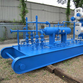
The Workhorse of the Field | The Horizontal Separator
A horizontal separator is a cylindrical vessel laid on its side. This orientation provides a much larger gas-liquid interface area compared to a vertical design of the same capacity. This feature is the key to its primary advantages and makes it the most common type of separator used in production facilities around the world.
The large surface area makes a horizontal separator exceptionally good at processing wellstreams with a high gas-to-oil ratio (GOR) and those that have a tendency to foam. The large, calm surface allows entrained gas bubbles to break out of the liquid phase more easily, and it provides more space for foam to collapse. The extended length of the vessel also provides a longer residence time for the liquids, allowing for very efficient separation of oil and water in three-phase configurations. For a given volume of gas to be processed, a horizontal design is often more economical than a vertical one. These factors make the horizontal separator the preferred choice for the majority of standard wellstream processing applications.
A Niche Player | The Spherical Separator
The least common, but still important, type is the spherical separator. As the name suggests, this vessel is a sphere. Its main advantages are that it is very compact, has a small footprint, and is generally the most economical design to manufacture for a given pressure rating. Spherical separators are also relatively easy to transport and install.
However, these advantages come with significant trade-offs. The internal design of a spherical separator provides very limited space for liquid collection and a small gas-liquid interface area. This makes them relatively inefficient separators and gives them very little capacity to handle surges in liquid flow. Controlling the liquid level within a sphere is also notoriously difficult.
Thanks to these limitations, their use is typically restricted to low to moderate flow rate applications where separation requirements are not stringent. They are often used as test separators or as compact gas scrubbers.
The Pro Gas LLC Difference | Excellence in Separator Design
Choosing the right separator is not as simple as picking a type off a list. It is a critical engineering decision that requires a thorough analysis of the specific wellstream conditions pressure, temperature, flow rates, GOR, water cut, and the presence of solids or foam. An improperly sized or selected separator will lead to poor separation, which can cause major problems downstream, such as damaged compressors, off-spec crude oil, and inaccurate production measurements.
This is where the expertise of Pro Gas LLC becomes invaluable. We don’t just sell equipment; we provide engineered solutions. Our team works closely with clients to analyze their unique operational data and recommend the ideal separator configuration whether it’s a vertical separator for a sandy well, a large horizontal separator for a high-GOR production facility, or a compact two-phase separator for a compressor station. Our commitment to excellence in separator design and fabrication, adhering to strict ASME standards, means you receive a piece of equipment built for safety, reliability, and maximum operational efficiency.
The gas separator stands as a foundational pillar in the field of oil and gas separation. It is the first and most crucial step in transforming a chaotic wellstream into valuable, manageable products. As we have seen, these vessels are not a one-size-fits-all solution. The choice between a two-phase separator and a three-phase separator, or between a vertical separator, horizontal separator, or spherical separator, depends entirely on the specific demands of the application.
Making the correct choice is fundamental to the success of your operation. A well-designed separation system, tailored to your specific needs, will protect your downstream equipment, improve your product quality, and maximize your profitability. At Pro Gas LLC, we are dedicated to providing that expertise. We are your partners in bringing order to chaos, delivering the robust, reliable separation solutions you need to power your success.
Are you facing challenges with your current separation process, or are you planning a new production facility? Don’t leave this critical decision to chance. Contact the separation experts at Pro Gas LLC today. We will help you analyze your needs and provide a detailed quote for a custom-engineered separator that is perfectly suited for your operation.
Frequently Asked Questions
Q. What is the main difference between a two-phase and a three-phase separator?
A two-phase separator divides the incoming stream into two parts gas and a combined liquid stream (oil and water mixed together). A three-phase separator divides the stream into three distinct parts gas, oil, and water, with separate outlets for each.
Q. When would I choose a vertical separator over a horizontal one?
You would typically choose a vertical separator for applications with a low gas-to-oil ratio, or when the wellstream is known to contain a high volume of solids like sand. Their smaller footprint also makes them ideal for locations with limited space, such as offshore platforms.
Q. What does GOR (Gas-to-Oil Ratio) mean and why does it affect separator choice?
GOR is the ratio of the volume of gas that comes out of solution to the volume of oil at standard conditions. A “high GOR” well produces a large amount of gas for every barrel of oil. Horizontal separators are generally better for high GOR streams because their large gas-liquid interface area allows the gas to separate from the liquid more efficiently.
Q. Are your separators built to industry standards?
Yes, absolutely. All Pro Gas pressure vessels, including our gas separators, are designed and fabricated in strict accordance with the American Society of Mechanical Engineers (ASME) Boiler and Pressure Vessel Code (BPVC), Section VIII. This is the primary standard governing the design and construction of pressure vessels for safety and reliability.